Mode Transition Circuit for Transferring Radio Frequency Signal and Transceiver Module Having the Same

Active Publication Date: 2008-12-04
ELECTRONICS & TELECOMM RES INST
View PDF5 Cites 27 Cited by
  • Summary
  • Abstract
  • Description
  • Claims
  • Application Information

AI Technical Summary

Benefits of technology

[0010]In the present invention, a waveguide is formed for integrating a radio frequency (RF) substrate and a low frequency substrate. Therefore, the signal loss generated while transferring a RF signal can be minimized according to the present invention.
[0011]According to the present invention, a baseband processor or a power IC of a low frequen

Problems solved by technology

Since the micro-strip line must include a conductive element such as a back-short, the micro-strip line is not proper in a view of miniaturizing a mode transition circuit.
However, a transmission line such as micro-strip line is still required to connect active elements and a mode transition circuit so the signal loss is unescapable due to the transmission line.
However,

Method used


Image

  • Mode Transition Circuit for Transferring Radio Frequency Signal and Transceiver Module Having the Same
  • Mode Transition Circuit for Transferring Radio Frequency Signal and Transceiver Module Having the Same
  • Mode Transition Circuit for Transferring Radio Frequency Signal and Transceiver Module Having the Same

Examples


Embodiment Construction

[0018]Other objects and aspects of the invention will become apparent from the following description of the embodiments with reference to the accompanying drawings, which is set forth hereinafter.

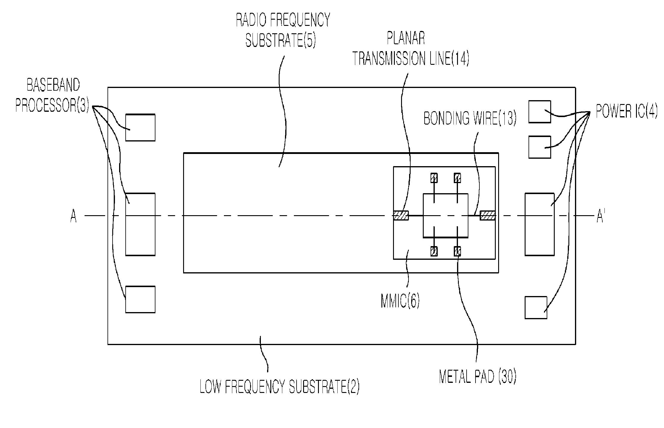
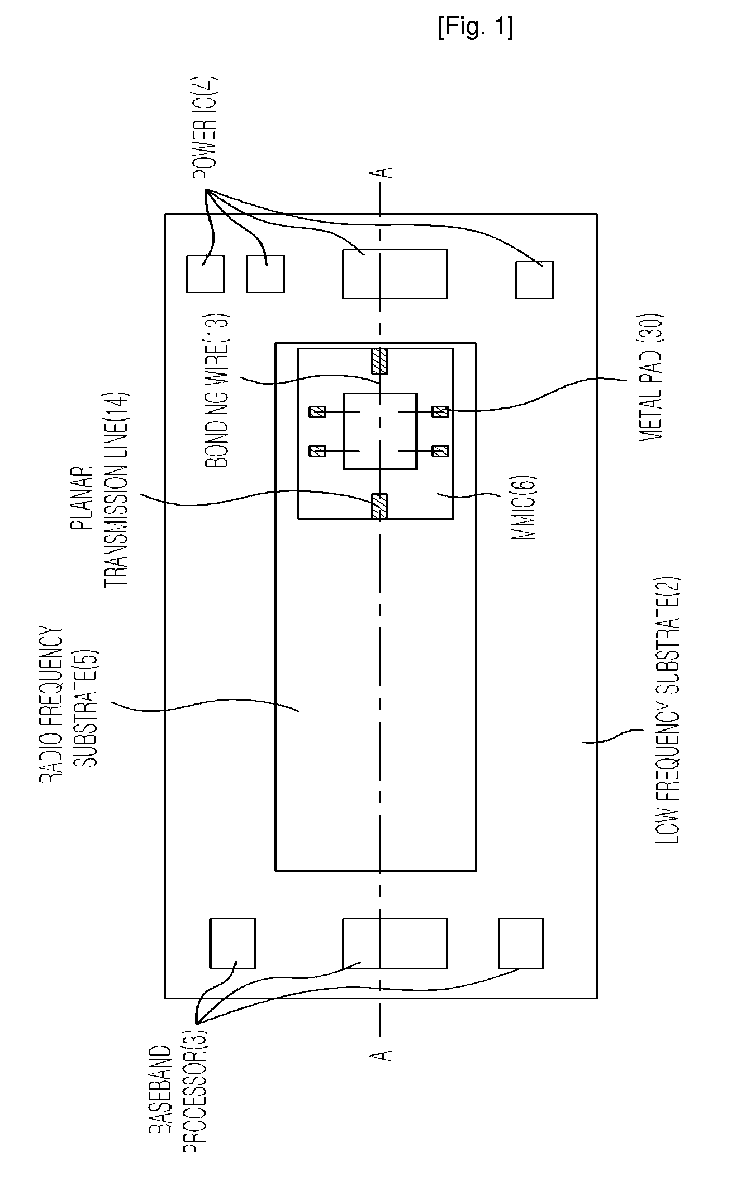
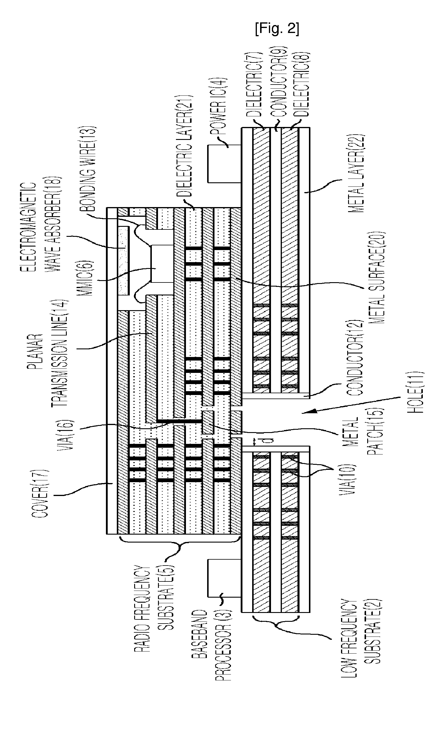
[0019]FIG. 1 is a top view illustrating a transition circuit for transferring a RF signal in accordance with an embodiment of the present invention, FIG. 2 is a cross-sectional view of FIG. 2 taken along the line A-A′ and FIG. 3 is a bottom view of FIG. 1.

[0020]The present invention proposes a mode transition circuit for transferring a Radio Frequency (RF) signal generated from a RF substrate 5 to a module such as an antenna through a planar transmission line 14 and a waveguide including vias 5 and metal patches 15 formed inside the RF substrate 5 and a hole 11 formed inside a low frequency substrate 2, and a transceiver module having the same.

[0021]As described above, the present invention proposes the mode transition circuit for transferring a RF signal and a transceiver module having the...


PUM


Abstract

Provided is a mode transition circuit for transferring a RF signal and a transceiver module having the same. The mode transition circuit includes: a planar transmission line mounted at a RF substrate for receiving a RF signal from a RF signal generating unit; a via formed inside the RF substrate and connected to one side of the planar transmission line for receiving the RF signal from the planar transmission line; at least one of metal patches formed inside the RF substrate and connected to the one side of the via for receiving the RF signal from the via; and a hole formed inside a low frequency substrate and connected to one side of the metal patch for receiving the RF signal from the metal patch.

Description

TECHNICAL FIELD[0001]The present invention relates to a mode transition circuit for transferring a radio frequency (RF) signal and a transceiver module having the same; and more particularly, to a mode transition circuit for transferring a Radio Frequency signal generated from a RF substrate to a module such as an antenna through a planar transmission line and a waveguide including vias and metal patches formed inside the RF substrate and a hole formed inside a low frequency substrate, and a transceiver module having the same.BACKGROUND ART[0002]A mode transition circuit for transferring a radio frequency (RF) signal and a transceiver module having the same are generally formed of a substrate having a predetermined dielectric constant that allows it to be operated in a RF domain. Particularly, the mode transition circuit is generally embodied using a micro-strip line to waveguide transition, which shows quasi TEM to TE01 mode transition. Since the micro-strip line must include a con...

Claims


Application Information

Patent Timeline
IPC IPC(8): H01P1/16
CPCH01P5/107H01P5/103H01P5/00
Inventor BYUN, WOO-JINKIM, KWANG-SEONKIM, BONG-SUEUN, KI-CHANSONG, MYUNG-SUN
Owner ELECTRONICS & TELECOMM RES INST
Why Eureka
Try Eureka