
Liquid crystal display apparatus and luminance control method thereof

a technology of luminance control and display apparatus, which is applied in the field of luminance control techniques of display apparatus, can solve problems such as bringing discomfort to the viewer, and achieve the effect of improving contras

Inactive Publication Date: 2008-12-04
HITACHI LTD
View PDF2 Cites 37 Cited by
  • Summary
  • Abstract
  • Description
  • Claims
  • Application Information

AI Technical Summary

Benefits of technology

The present invention is a liquid crystal display apparatus that can extract the luminance distribution of an input video signal and the pixel frequency distribution of specific color in a screen area. It can then determine the control amount of the luminance of the plurality of backlights and the correction amount of the luminance of the liquid crystal panel for the screen area. By controlling the luminance of the plurality of backlights and the luminance of the input video signal, the apparatus can achieve uniform luminance on the screen and improve the contrast. This technique can reduce the discomfort caused by changes in luminance and hue of light in the displayed video.

Problems solved by technology

Because the eyes of a human being are in particular sensitive to the difference in the luminance and hue of light brown (skin color), the person's face whose luminance has changed will bring discomfort to the viewer.

Method used


Image

  • Liquid crystal display apparatus and luminance control method thereof
  • Liquid crystal display apparatus and luminance control method thereof
  • Liquid crystal display apparatus and luminance control method thereof

Examples


Embodiment Construction

[0020]Embodiments of the present invention will be described with reference to drawings as below.

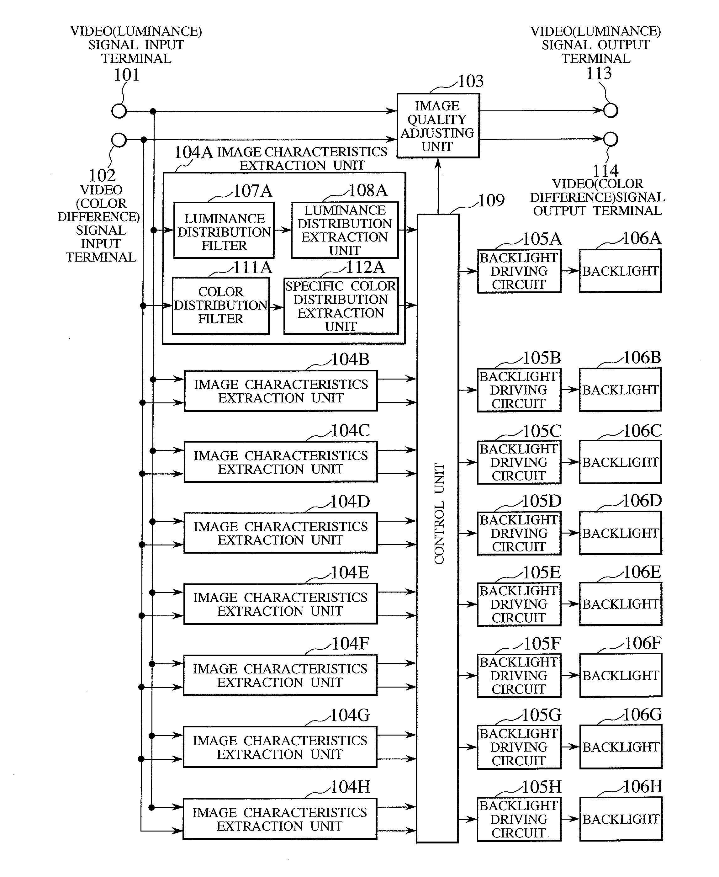
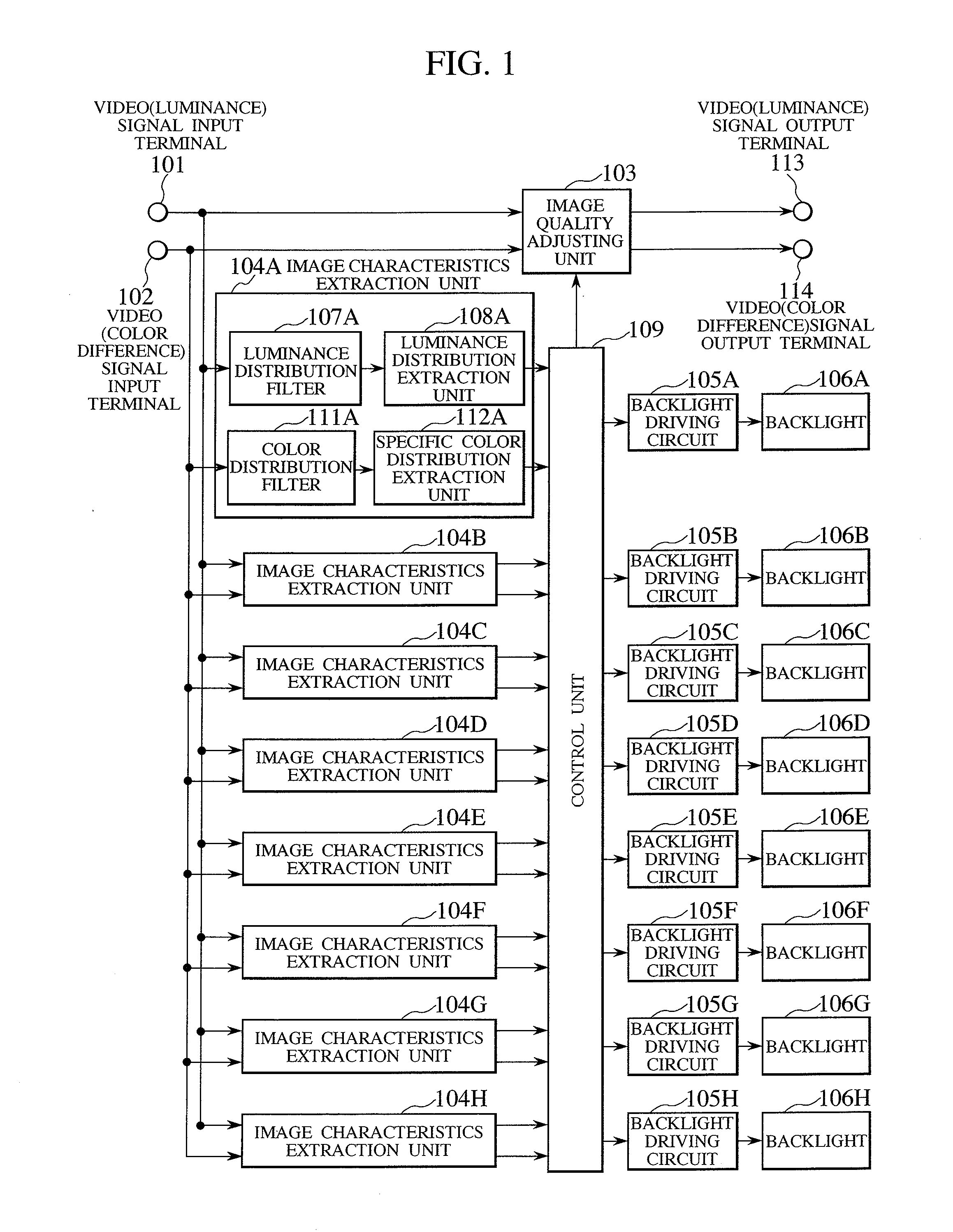
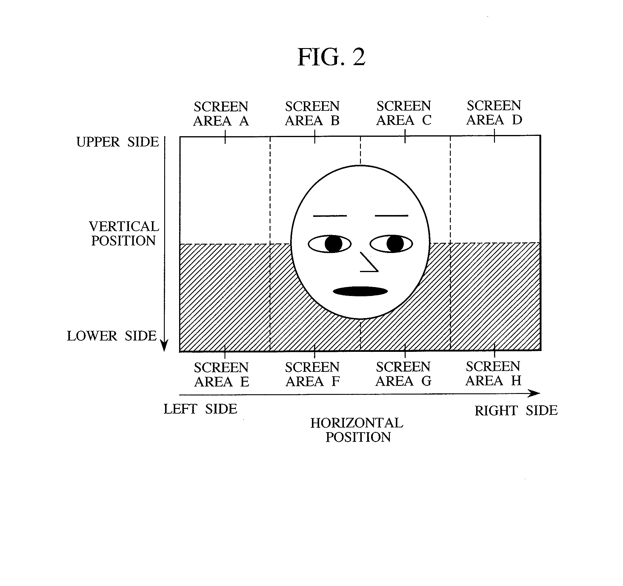
[0021]FIGS. 1 through 8 are diagrams each illustrating a liquid crystal display apparatus according to one embodiment of the present invention. FIG. 1 is a diagram illustrating as an example a configuration of the liquid crystal display apparatus according to the embodiment of the present invention. FIG. 2 is a diagram illustrating how a screen of the liquid crystal display apparatus shown FIG. 1 is divided into screen areas. FIGS. 3A through 3H are charts each illustrating characteristics of a luminance distribution filter included in the liquid crystal display apparatus shown in FIG. 1. FIGS. 4A through 4H are charts each illustrating, on a luminance level basis, the pixel frequency distribution of the image shown in FIG. 2. FIGS. 5A through 5H are charts each illustrating characteristics of a color distribution filter included in the liquid crystal display apparatus shown in FIG. 1. F...


PUM

PropertyMeasurementUnit
pixel frequency distributionaaaaaaaaaa
coloraaaaaaaaaa
luminance distributionaaaaaaaaaa

Abstract

For the purpose of suppressing untrue black with the change in luminance of video, which is displayed as the same object, being reduced to improve the contrast, there is provided a liquid crystal display apparatus that is capable of: extracting the pixel frequency distribution of an input video signal on a luminance level basis, and extracting the pixel frequency distribution of specific color from a color-difference signal of input video in a screen area, the color-difference signal being determined from the luminance distribution of a plurality of backlights; on the basis of the result of the extraction, determining the control amount of the luminance of the plurality of backlights, and the correction amount of the luminance of a liquid crystal panel, on a screen area basis; controlling the luminance of the plurality of backlights on the basis of the control amount of the luminance; and at the same time, controlling the luminance of the input video signal on the basis of the correction amount of the luminance.

Description

CLAIM OF PRIORITY[0001]The present application claims priority from Japanese application serial No. P2007-011526, filed on Jan. 22, 2007, the content of which is hereby incorporated by reference into this application.BACKGROUND OF THE INVENTION[0002]1. Technical Field of the Invention[0003]The present invention relates to liquid crystal display apparatuses, and more particularly to luminance control techniques thereof.[0004]2. Description of the Related Art[0005]In recent years, transmissive liquid crystal display apparatuses are achieving widespread use as large-screen flat televisions and large-screen flat displays. The transmissive liquid crystal display apparatus is configured to use, in combination, a liquid crystal panel functioning as an optical isolation shutter, and light source units located on the back of the liquid crystal panel. Each of the light source units is called “backlight”. The increase and decrease of the light quantity of each backlight causes the maximum lumi...

Claims


Application Information

Patent Timeline
Patent Type & Authority Applications(United States)
IPC IPC(8): G09G3/36G02F1/13357
CPCG09G3/3426G09G3/3611G09G2320/0646G09G2320/066H04N21/44008H04N5/57H04N5/66H04N9/68H04N21/4318G09G2360/16
Inventor TSURU, YASUTAKAOUCHI, SATOSHIMURATA, SEIJINAGAYOSHI, MAYUMI
Owner HITACHI LTD
Learn More