[0008]The present invention has been developed to solve such conventional problems, and a main object of the present invention is to provide a separate / integral type monitor device in which separation and
assembly in to one unit can be performed when required, in which water drops or the like do not enter into the respective insides of the screen display section and the control section even in poor weather, and in which separation operation and integration operation can be performed safely and easily, in a specific configuration.
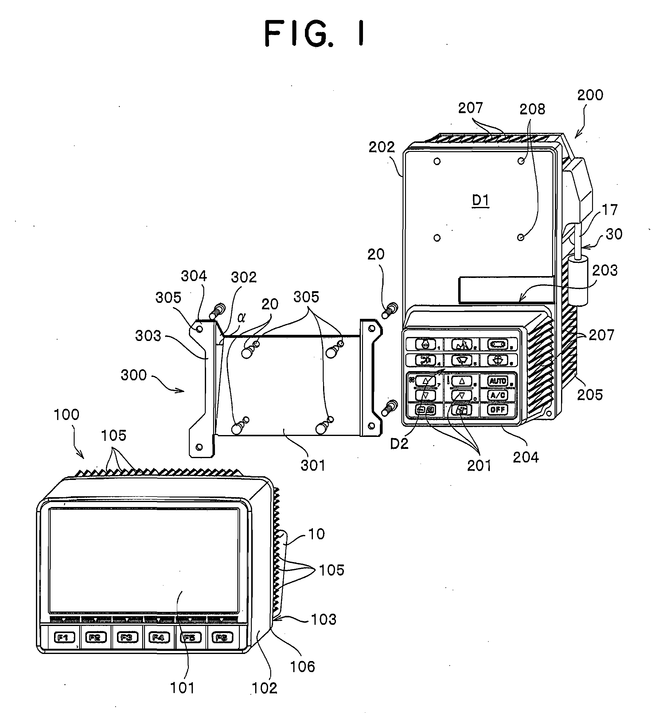
[0015]According to a request by an operator, the screen display section and the control section which are integrally assembled into one body through the bracket and which are formed into panel bodies independently are removed from the bracket to be separated from each other, or the respective separated screen display section and control section are secured to the securing section of the bracket to be integrated into one unit. In this way, since the screen display section and the control section can be separated and integrated, the separated screen display section may be arranged on a position spaced apart from the control section and the installation position of the integrated screen display section and the control section may be changed arbitrarily. Thus, at any time, the operator can arrange the screen display section and the control section at a position where operation and confirmation are easy. At this time
electrical connection between the screen display section and the control section is made by means of a connector having a harness, and when the screen display section and the control section are used as one unit, a
short length connector having a harness is employed, so that connector parts of their both ends can be directly connected with the control section. When the screen display section and the control section are used as separate units, the screen display section and the control section are connected via another connector having a harness between the
short length connectors having a harness.
[0016]When the screen display section and the control section have liquid-tight structures, in a monitor device which is disposed on a construction
machine or the like which is often operated while the window or door of the cab is opened at a place where environmental conditions are particularly poor, although water of rain or the like and fine particles and the like from the outer side are likely to hit the monitor device, rain and fine particles do not enter into the inside of the case body, and the long-term use of equipments for display driving and a controller composed of an integral circuit or the like in the case body can be assured. At the same time, even if water drops try to enter into an independent space in which the connector having a harness is accommodated, it can be prevented securely; therefore, waterproof property of the connector itself does not have to be considered, so that a commercially available, general connector can be employed.
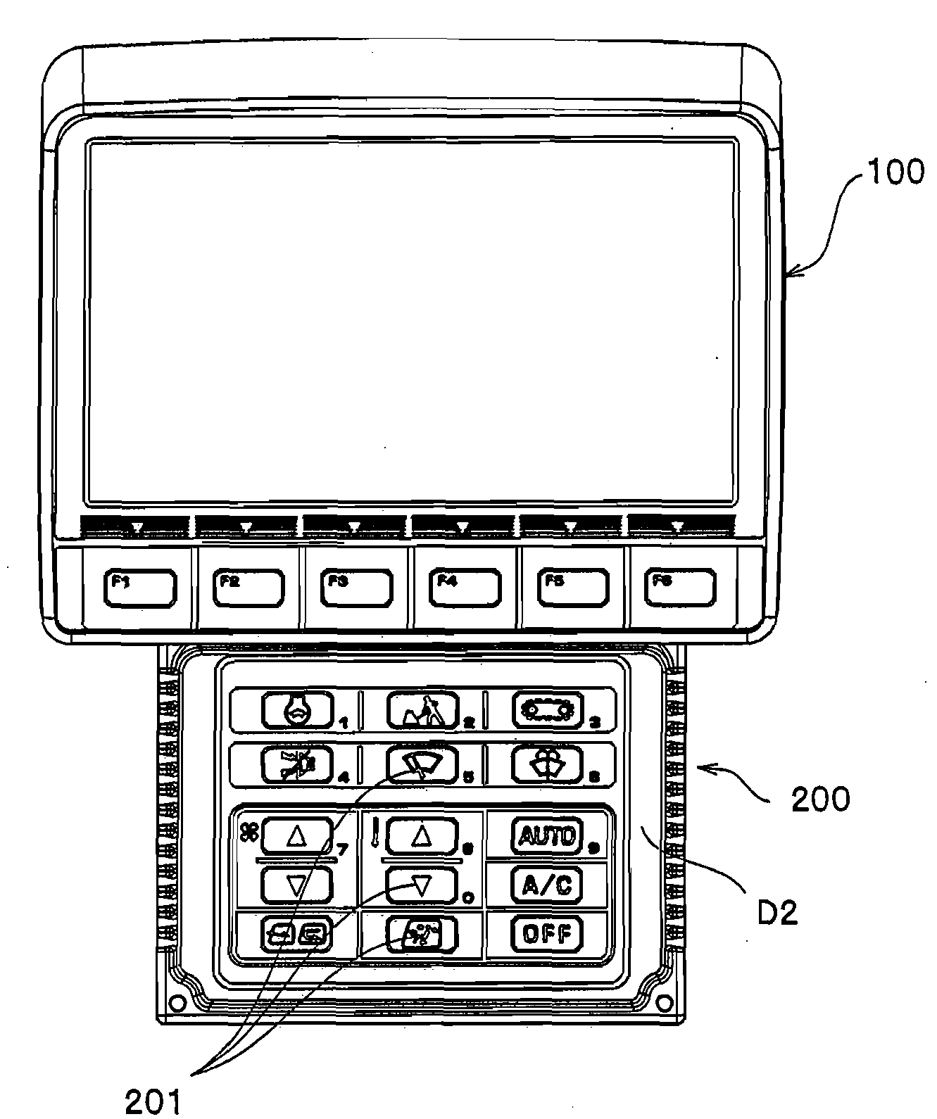
[0019]Regarding this, according to the preferred aspect of the present invention, an extra space is generated in the space accommodating the display driving equipments for the part for which the display panel of the screen display section is enlarged. Further, regarding the control section also, the display section supporting area which is regarded as a screen display section originally and the switch installation area are formed on the same surface as described above, so that the part of the screen display section enlarges the inner space of the control section. In the present invention, the respective spaces enlarged in this way are employed as spaces dedicated to accommodate the connectors which is for connecting the display driving equipments and respective terminals of the controller. Their formation positions should be a corner part of the first panel and a corner part of a position where the first panel is superimposed on the first panel supporting area of the second panel through the bracket. In this way, the harness that is an electric connection line between the screen display section and the control section can be short, and when the first and second panels are assembled through the bracket, the harness does not become a hindrance. Further, when the respective connectors having a harness accommodating spaces are liquid-tight, as described above, commercially available, regular connectors having a harness can be employed.
[0020]When the
insertion / detachment opening of the connector having a harness is closed by means of the lid body, although water which tries to enter into a gap between the same
insertion / detachment opening and the lid body enters into the seal groove formed on the periphery of the
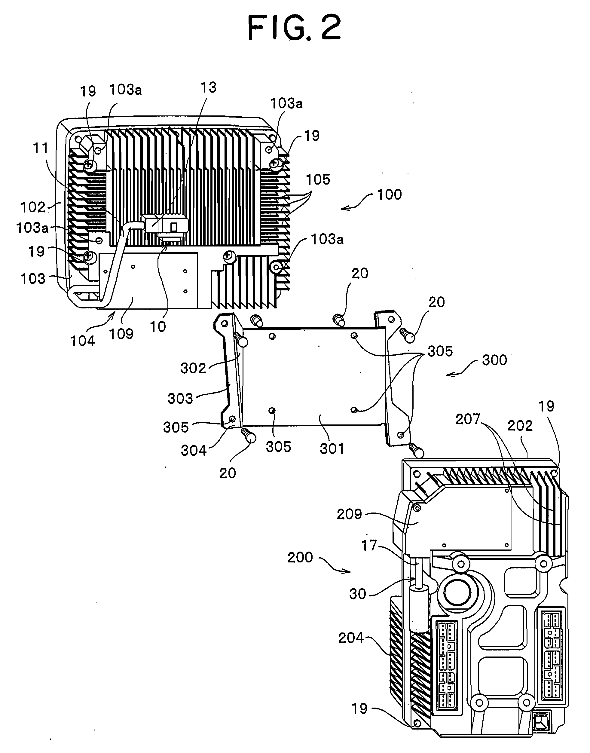
insertion / detachment opening, it is blocked by means of the projection like frame portion formed inside the seal groove, and it does not enter into the above-described space. In order to separate or integrally assemble the screen display section and the control section via the bracket, the first and second flanges of the bracket are attached to the rear surface of the screen display section and the display section supporting part of the control section respectively, and the screws are inserted into the screw-through holes of the respective flanges. Then, the same screws are screwed into screw bores which correspond to the screen display section and the control section to assemble them into one unit, and these screws are removed to allow the screen display section and the control section to be removed from the bracket. When the screen display section and the control section are assembled into one unit, since the bracket has a triangular shape in the side view thereof, the front surface of the screen display section faces in a slant forward direction with respect to the control section arranged horizontally, so that view and recognition properties of the image displayed on the screen can be improved. When the screw-through holes are formed into long holes or H-shaped holes, the relative fixing position between the screen display section and the control section can be easily changed.

