Liquid-lens variable-control optics in array microscope

Inactive Publication Date: 2008-12-04
DMETRIX INC
View PDF10 Cites 39 Cited by
  • Summary
  • Abstract
  • Description
  • Claims
  • Application Information

AI Technical Summary

Benefits of technology

[0008]The heart of the invention lies in a novel combination of features that make it possible to construct a liquid-lens cell that can be controlled to correct fabrication aberrations and to adjust the lens's focal length over a useful range w

Problems solved by technology

Therefore, such an array of passive imaging elements suffers from the limitation that its finite area is greater than the local variation of topography on the sample being scanned.
In t

Method used


Image

  • Liquid-lens variable-control optics in array microscope
  • Liquid-lens variable-control optics in array microscope
  • Liquid-lens variable-control optics in array microscope

Examples


Example

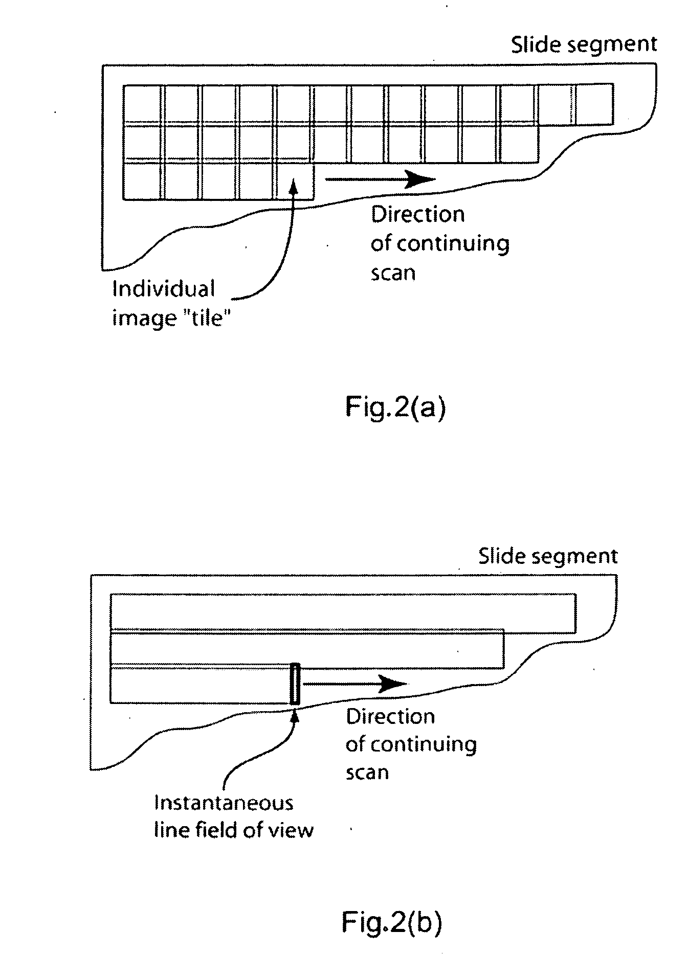
[0025]Existing microscope optics enable two principal image-acquisition approaches. These approaches are represented in every whole slide scanning system available commercially. There is a “step-and-repeat” approach in which individual image fields (also known as “tiles”) are recorded and the stage bearing the microscope slide is advanced to the next field, as illustrated in FIG. 2(a). For a typical 20× field-flattened objective, this approach results in several thousand image fields for a 20 mm by 50 mm virtual slide, depending on how much field overlap is provided and whether a complete record of the slide is made. The other approach is to use a linear detector array covering the diameter of the field of view of the microscope objective. This results in a swath that could cover the entire width of a slide, to be repeated, after a step-over, for a 50 mm long slide (typically 50 times). This approach, illustrated in FIG. 2(b), is sometimes referred to as “push-broom” scanning.

[0026]...


PUM


Abstract

A liquid lens includes a segmented electrode that allows the simultaneous application of different potentials across the lens's meniscus to obtain a predetermined aberration correction condition and to adjust focal length as necessary to conform to the topography of the object being scanned. The lens also includes a gas plenum interfacing with one of the liquids of the lens to allow for volume changes in the lens cell due to temperature variations. This combination of features produces a liquid-lens cell capable of maintaining substantially constant transverse magnification and diffraction-limited image quality over a useful range of focal length. As such, the lens is particularly suitable for incorporation in an array of micro-objectives used in a scanning microscope.

Description

RELATED APPLICATIONS[0001]This application is based on and claims the priority of Provisional Application No. 60 / 898,215, filed Jan. 30, 2007.BACKGROUND OF THE INVENTION[0002]1. Field of the Invention[0003]This invention relates in general to the field of array microscopy and, in particular, to the use of variable-focus liquid lenses for providing programmable optics to correct aberrations, ensure uniform performance of the array, and focus dynamically during the scan of uneven surfaces.[0004]2. Description of the Prior Art[0005]Array microscopes image a sample surface by scanning linearly over the sample. The microscopes of the array acquire intensity data corresponding to adjacent strips of the sample surface, thereby providing a complete image of the sample with a single scan. Each microscope consists of a fixed combination of optical elements with the same design characteristics. Accordingly, each microscope exhibits the same optical performance, subject to tolerances and imperf...

Claims


Application Information

Patent Timeline
IPC IPC(8): G02B3/14G02B21/02B29D11/00
CPCB29D11/00028B29D11/00807G02B3/0012G02B3/0056G02B3/14G02B21/002G02B21/02
Inventor CHRISTENSON, TODD C.DESCOUR, MICHAEL R.LIANG, CHENOLSZAK, ARTUR G.
Owner DMETRIX INC
Why Eureka
Try Eureka