Plasma display apparatus

a technology of display apparatus and plasma, which is applied in the direction of identification means, electrical apparatus casings/cabinets/drawers, instruments, etc., can solve problems such as the malfunction of external devices, and achieve the effect of reducing the emission of generated electromagnetic waves

Inactive Publication Date: 2008-12-04
SAMSUNG SDI CO LTD
View PDF5 Cites 19 Cited by
  • Summary
  • Abstract
  • Description
  • Claims
  • Application Information

AI Technical Summary

Benefits of technology

[0007]It is therefore a feature of an embodiment of the present invention to provide a plasma display appa...

Problems solved by technology

Emission of the electromagnetic waves outside the plasma display apparatus may be harmful to...

Method used


Image

  • Plasma display apparatus
  • Plasma display apparatus
  • Plasma display apparatus

Examples


examples

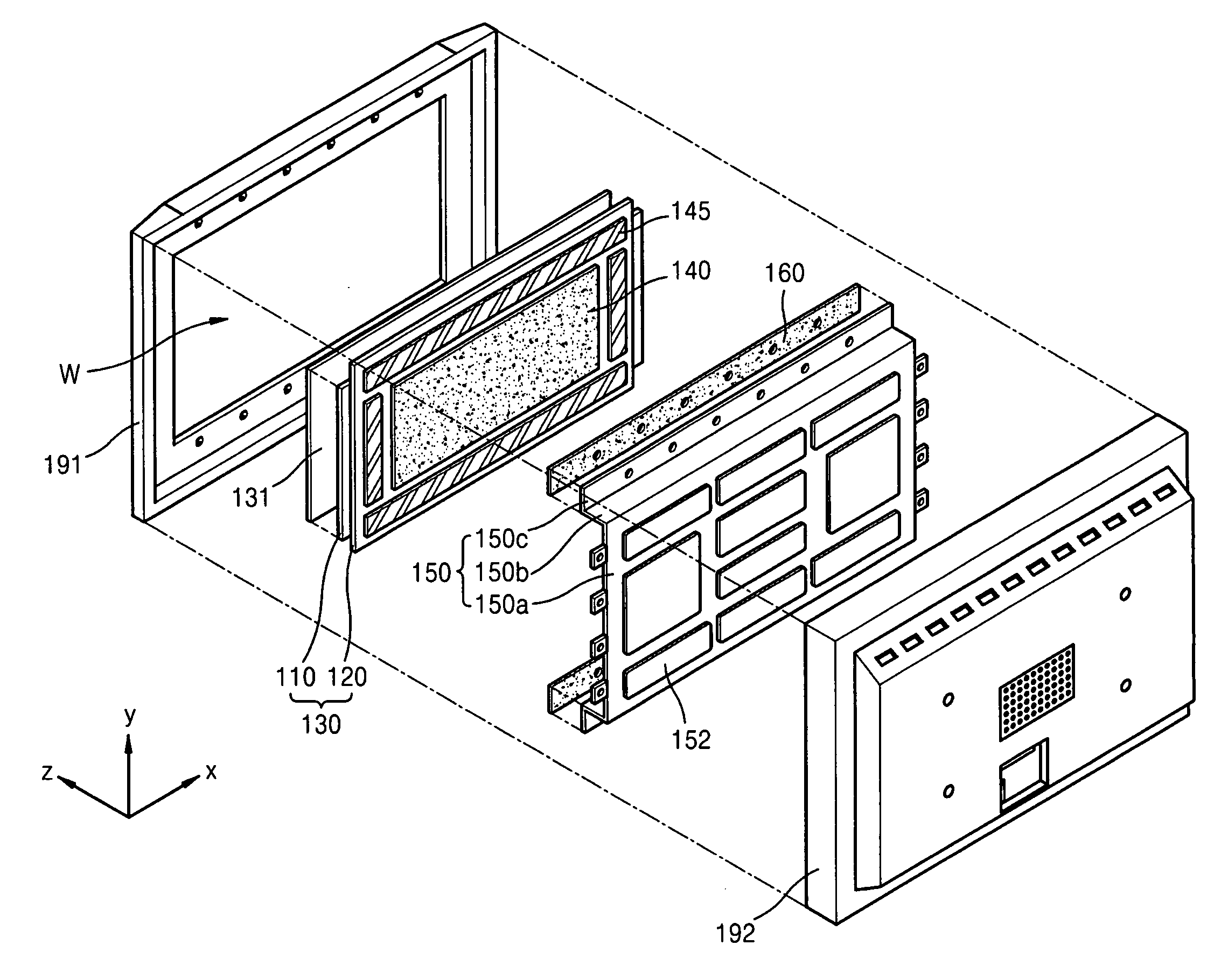
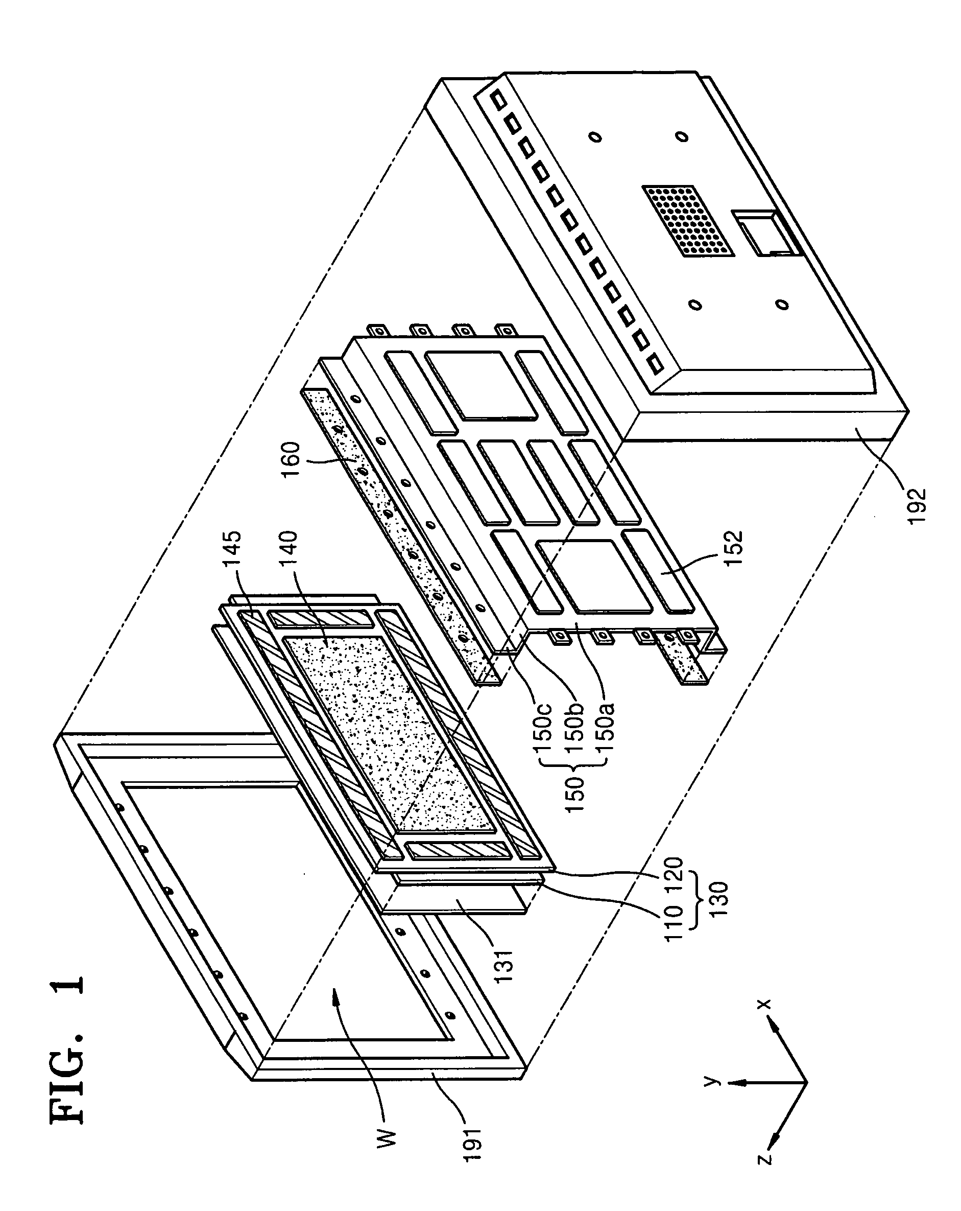
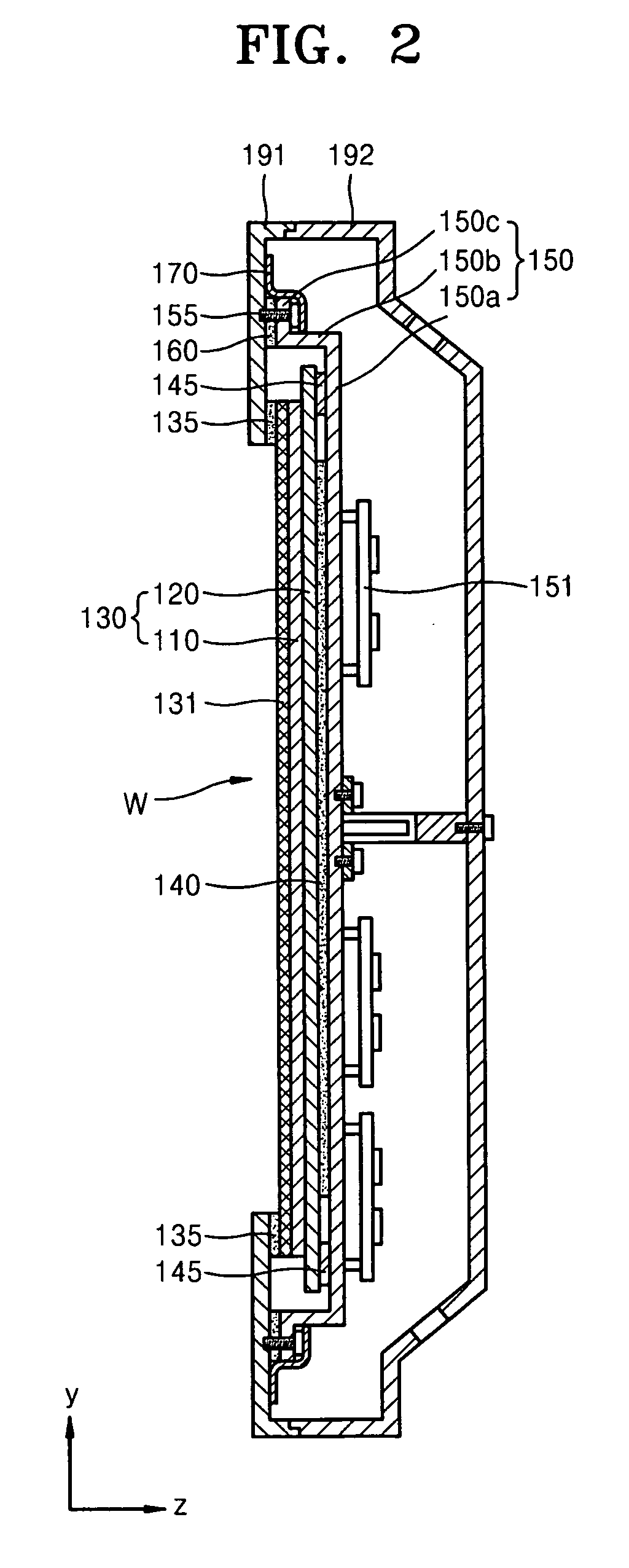
[0039]Two plasma display apparatuses according to embodiments of the present invention were formed and evaluated in terms of emission of electromagnetic waves outside the plasma display apparatuses. The first plasma display apparatus, i.e., Example 1, was formed according to the embodiment illustrated in FIG. 5, i.e., a plasma display apparatus including a flange unit directly attached to the front cover. The second plasma display apparatus, i.e., Example 2, was formed according to the embodiment illustrated in FIGS. 1-3, i.e., a plasma display apparatus including a flange unit including a continuous conductive gasket providing a reinforced surface grounding between the front cover and the chassis and a conductive tape 170.

[0040]Electromagnetic waves in a frequency band of about 30 MHz to about 300 MHz in each of the two plasma display apparatuses were measured. Results are reported in Table 1 below and in FIGS. 6A-6B.

TABLE 1Valuemax at overallValuemax at Low FrequencyFrequencyExamp...


PUM


Abstract

A plasma display apparatus includes a front case coupled to a rear case, the front and rear cases facing each other, a plasma display panel between the front and rear cases, and a chassis attached to the front case, the chassis being between the plasma display panel and the rear case, and the chassis including, a base unit parallel to the plasma display panel, at least one flange unit on the front case, the flange being parallel to the base unit and spaced apart from the base unit, and at least one shielding unit connecting the base unit with the flange unit, the shielding unit covering sides of the plasma display panel.

Description

BACKGROUND OF THE INVENTION[0001]1. Field of the Invention[0002]Embodiments of the present invention relate to a plasma display apparatus. More particularly, embodiments of the present invention relate to a plasma display apparatus having a structure capable of reducing emission of generated electromagnetic waves to an exterior thereof.[0003]2. Description of the Related Art[0004]A plasma display apparatus may include a plasma display panel (PDP) that displays images by a gas discharge. A conventional PDP may include first and second substrates, discharge electrodes between the first and second substrates, and a discharge gas in a plurality of discharge cells between the first and second substrates. Driving signals may be supplied to the discharge gas via the discharge electrodes to generate a discharge between the first and second substrates, so emission of visible light may be triggered to form images.[0005]Generation of discharge, however, may include generation of electromagneti...

Claims


Application Information

Patent Timeline
IPC IPC(8): G06F1/16G09G3/28
CPCG06F1/1601G09G3/28G09G2330/06H05K9/0054G09F9/313H01J11/34H01J11/46
Inventor PYO, KYUNG-RAE
Owner SAMSUNG SDI CO LTD
Why Eureka
Try Eureka