Gateway device, optical network terminal, and passive optical network system

a gateway device and optical network terminal technology, applied in the field of voice gateway devices, can solve the problems of all telephone services to be stopped, serious affecting the services provided using the telephone network,

Inactive Publication Date: 2008-12-04
HITACHI LTD
View PDF7 Cites 27 Cited by
  • Summary
  • Abstract
  • Description
  • Claims
  • Application Information

AI Technical Summary

Benefits of technology

[0015]The voice gateway according to the present invention can, even when an associated telephone network fails, keep calls between telephones connected to ONTs which are connected to an associated OLT active and make new call connections between telephones belonging to such ONTs.

Problems solved by technology

In the network operating format (A), however, a failure of the existing telephone network integrated in a broadband Internet access service providing telephone services causes all the telephone services to be stopped.
Generally, up to several thousand subscriber telephones are connected to one OLT, so that a connection line failure between an OLT and a telephone network can seriously affect the services provided using the telephone network.

Method used


Image

  • Gateway device, optical network terminal, and passive optical network system
  • Gateway device, optical network terminal, and passive optical network system
  • Gateway device, optical network terminal, and passive optical network system

Examples


first embodiment

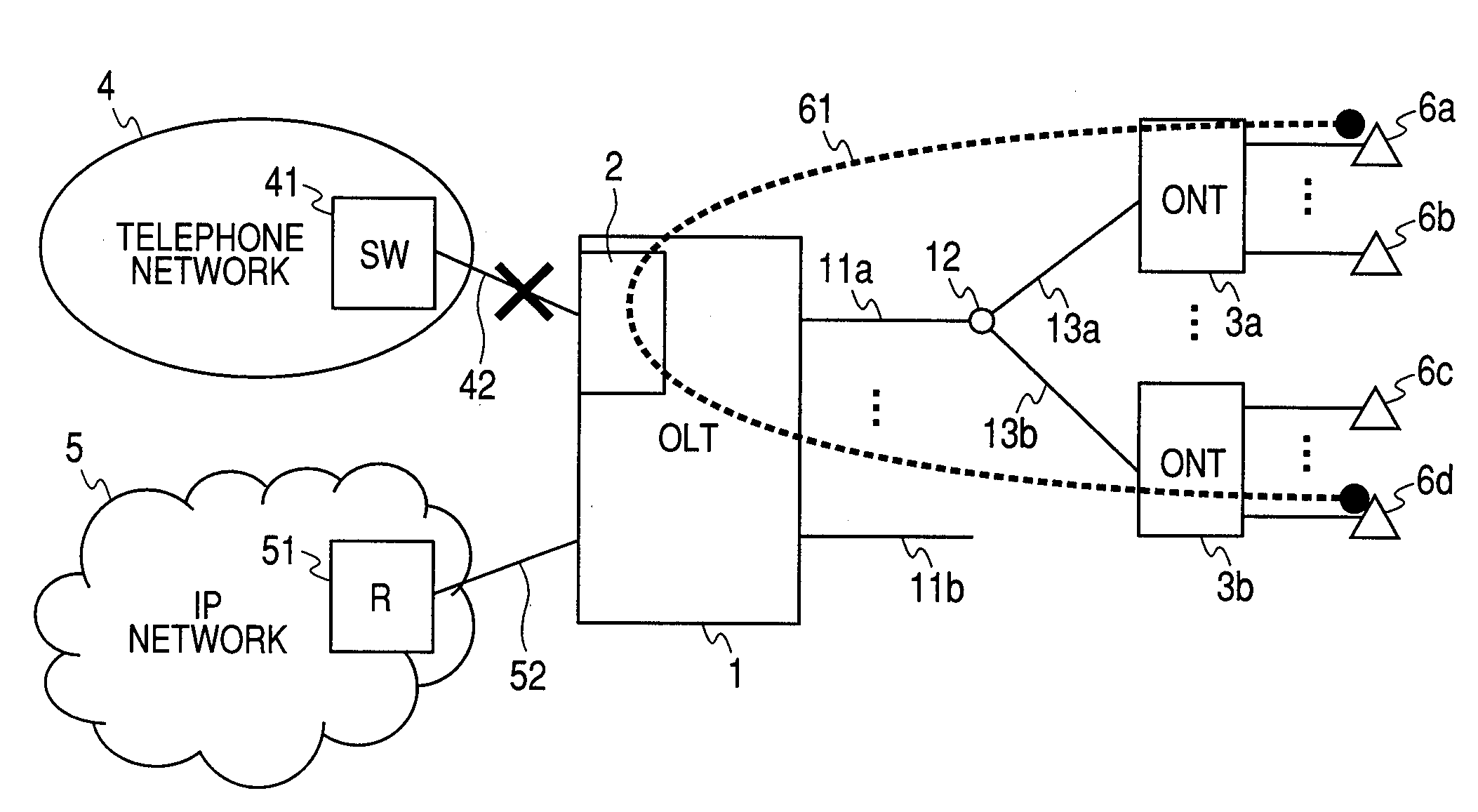
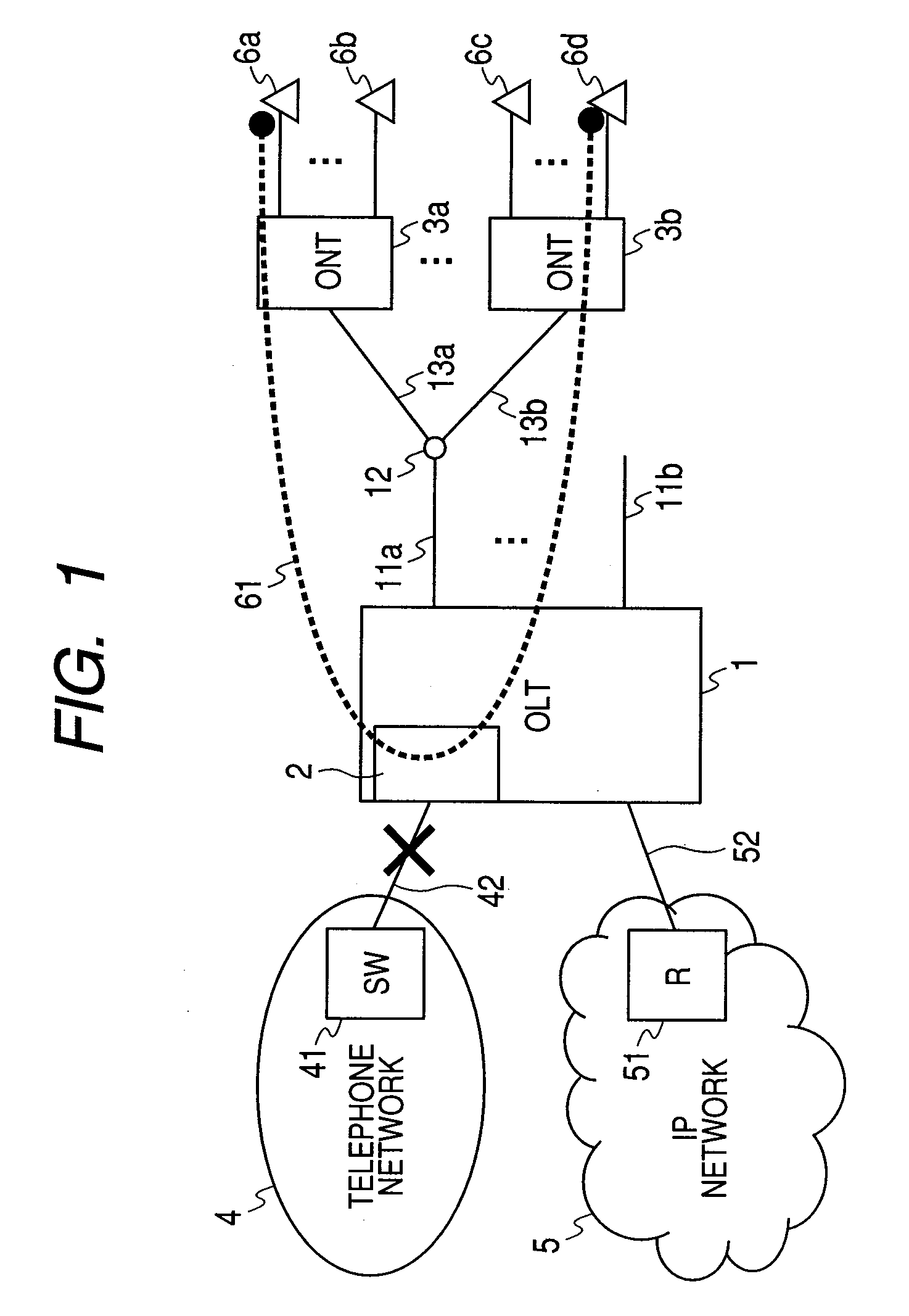
[0043]FIG. 1 is a diagram showing an example configuration of a broadband access network to which the present invention is applied. In FIG. 1, how application of the present invention enables a telephone service to be continued at a time of a network failure is illustrated. In the example case illustrated in FIG. 1, a telephone connection service is continued even after a line 42 between a telephone network 4 and an OLT (optical line terminator) 1 fails.

[0044]The OLT 1 installed in a broadband access network accommodates an optical fiber 11a, a splitter 12 which branches and multiplexes an optical signal, and ONTs (optical network terminals) 3a to 3b installed in subscribers' homes via optical fibers 13a to 13b. The OLT 1 is connected to a telephone switch 41 included in the telephone network 4 via a line 42 and to a router 51 included in the IP network 5 via a line 52. Reference numeral 2 denotes a voice gateway (hereinafter referred to as the “VGW”) connecting the OLT 1 and the te...

second embodiment

[0078]FIG. 23 shows a second embodiment of the present invention. The second embodiment differs from the first embodiment in that an SIP server function is realized not in the VGW 2 but in an SIP server 59 included in an IP network 5. In FIG. 24, reference numeral 69 denotes a flow of telephone voice data between a telephone 6a belonging to an ONT 3a and a telephone 6b belonging to an ONT 3b. In this embodiment, the voice data is looped back in the IP network 5. Therefore, as shown in FIG. 23, a logical path for transferring voice data is set up between a packet interface 15 included in an OLT 1 and each of the ONTs 3a to 3b. In the example shown in FIG. 23, a logical path 72a is set up between the packet interface 15 and the ONT 3a, and a logical path 72b is set up between the packet interface 15 and the ONT 3b. To enable packets to be transferred from the packet interface 15 to the ONTs, MAC-path information 159 is included in the packet interface 15 of the OLT 1. The MAC-path inf...


PUM

PropertyMeasurementUnit
timeaaaaaaaaaa

Abstract

In a broadband access network, calls can be kept active even when a telephone network fails. A voice gateway function captures callee telephone number information sent from a caller subscriber telephone to the telephone network and, when the telephone network fails, keeps the call active by retaining the connection between the caller and the callee. Furthermore, when the telephone network fails, the operation mode of the voice gateway and all ONTs is switched from an H.248 gateway mode to an SIP softswitch mode, allowing the voice gateway function to relay communication packets between ONTs and new call connections to be made in the broadband access network.

Description

CLAIM OF PRIORITY[0001]The present application claims priority from Japanese application JP 2007-146425 filed on Jun. 1, 2007, the content of which is hereby incorporated by reference into this application.FIELD OF THE INVENTION[0002]The present invention relates to a voice gateway device which, in a broadband access network, can keep a call active even when a telephone network fails.BACKGROUND OF THE INVENTION[0003]As high-quality broadband Internet access services using optical fibers are disseminated, services to integrate a traditional telephone service into an Internet access service have been increasing. Such integration services realize a telephone service using Internet access lines without using telephone lines connected into subscribers' homes. A telephone service can be integrated into an Internet access network by, broadly classified, the following two methods:[0004](1) Configuring softswitch using SIP (RFC3261: Session Initiation Protocol) and H.248 / Megaco (RFC3525: Gat...

Claims


Application Information

Patent Timeline
Patent Type & Authority Applications(United States)
IPC IPC(8): G02F1/00
CPCH04L12/2861H04L12/287H04M7/123H04Q11/0067H04Q2011/0088H04Q2213/1301
Inventor TAKIHIRO, MASATOSHIYOSHIDA, TAKAHIROTAKAHASHI, TETSUHIKOMITSUI, YUISHII, RYUJI
Owner HITACHI LTD
Why Eureka
Try Eureka