Micro-Air Motor

Inactive Publication Date: 2008-12-04
ROTOMED
View PDF12 Cites 2 Cited by
  • Summary
  • Abstract
  • Description
  • Claims
  • Application Information

AI Technical Summary

Benefits of technology

[0013]The inlet and outlet apertures advantageously have different cross sections. As a result, these can be optimally adapted to the requirements, i.e. the outlet apertures in the region of the outflowing exhaust air can be dimensioned substantially larger than the inlet apertures in the region of the supply air inflowing with high pressure. Thus the air resistance can be optimally maintained over the entire flow path.
[0014]Practically the inlet and/or outlet apertures are designed kidney-shaped. In interaction with the working chamber of the air motor which is usually ring or wedge-shaped this produces favourable flow conditions at the transition points of the collector to the rotor in all positions of twist of the collector.
[0015]Since the compressed air to the rotor is supplied and discharged usually axially, it is advantageous that at least one channel is oriented coaxially or parallel to the axis of the rotor. Such an arrangement also makes possible a compact and slim design of the compressed air motor or

Problems solved by technology

If the inlet and outlet apertures are identically dimensioned direction of rotation reversal is possible but the device does not generate the optimum but only a limited o

Method used


Image

  • Micro-Air Motor
  • Micro-Air Motor
  • Micro-Air Motor

Examples


Embodiment Construction

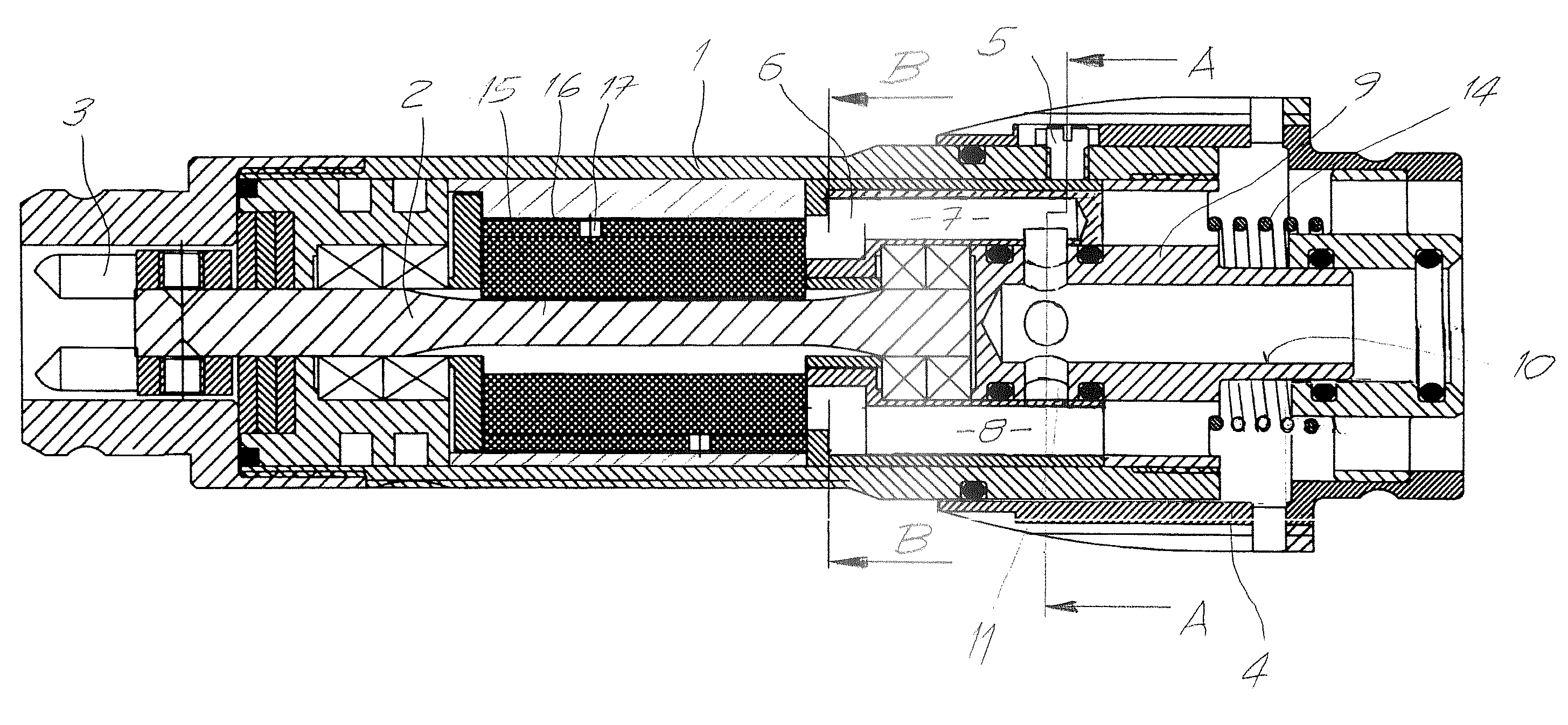
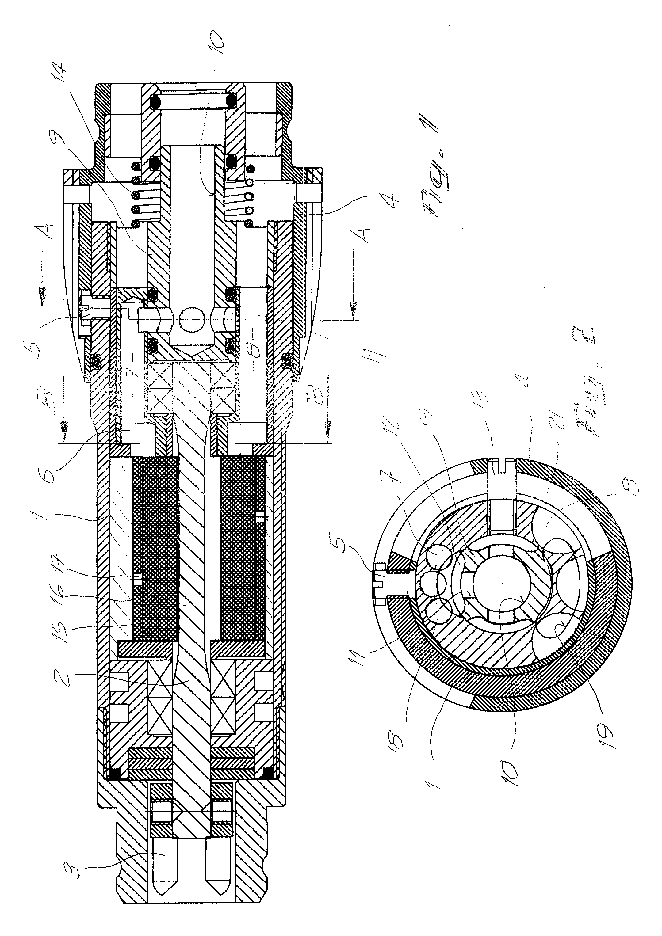
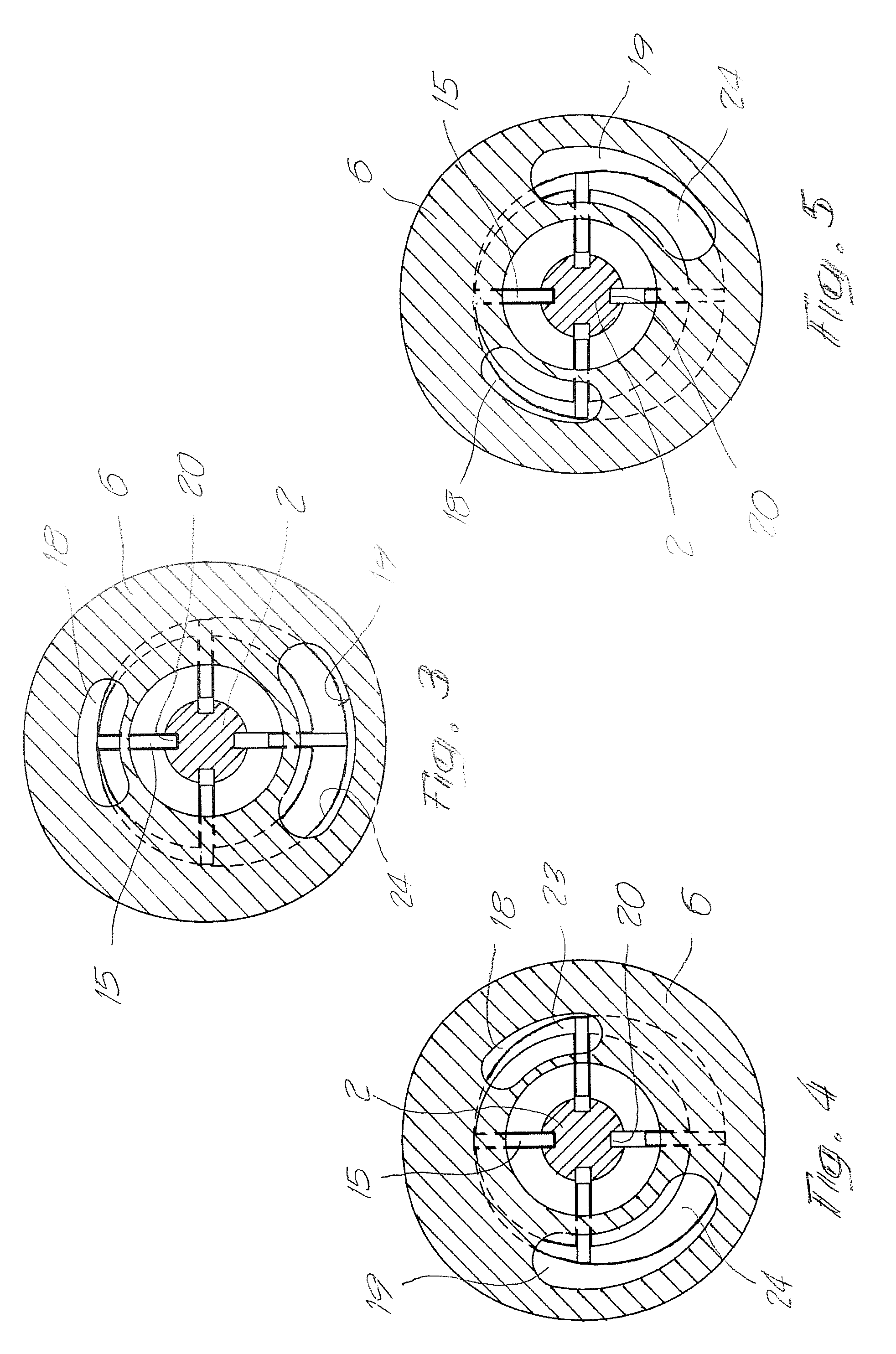
[0026]The micro-air motor shown in FIG. 1 to FIG. 5 comprises a casing 1 with a rotor 2 rotatably mounted in said casing. The free end of the rotor 2 is connected with a tool holder 3 for accommodating exchangeable tools. At its rearward end the casing 1 is surrounded by an actuation sleeve 4. The actuation sleeve 4 is axially displaceable to a limited extent against the force of a spring 14 and in the process also controls the compressed air supply. A stop 5 limits the axial displacement path of the actuation sleeve 4. In the casing 1 a collector 6 is mounted capable of being twisted to a limited extent.

[0027]The collector 6 comprises longitudinal bores 7 and channels 8 oriented in axial direction which are open towards the outside for the compressed air supply and discharge. An adapter 9 is securely connected with the housing 1. The adapter 9 is provided with a central bore 10 as well as with transverse bores 11 terminating in the central bore 10. Through milled portions 12 the co...


PUM


Abstract

A micro-air motor comprises a collector rotatably mounted in a casing for the compressed air supply and discharge to or from the rotor. By twisting the collector as far the end positions a direction of rotation reversal as well as continuous speed regulation is possible. In a neutral position of the collector the rotor can be additionally stopped and locked.

Description

BACKGROUND[0001]The invention relates to a micro-air motor with a casing comprising a guide bore and a rotor rotatably mounted therein, wherein the rotor is provided with slots substantially oriented radially outwards, in which plate-shaped vanes are mounted radially displaceable outwards through the centrifugal force and a collector axially following the rotor with inlet and outlet apertures and with channels connected to external connections for the compressed air, wherein the collector (6) is rotatably arranged about the axis of rotation of the rotor (2) or about an axis parallel to said rotor or about the longitudinal axis of the casing (1) by means of an actuation sleeve (4).[0002]Air motors with radially displaceable vanes are built and used in different sizes and for quite different applications. The devices designated “micro-air motors” as a rule have a casing diameter of less than two centimetres and are predominantly used in medical equipment, more preferably surgery and n...

Claims


Application Information

Patent Timeline
IPC IPC(8): F03B3/18
CPCA61B17/320758A61C1/05F01C1/348F05C2253/04F01C20/04F01C20/14F01C21/0809F01C13/02
Inventor MUELLER, THOMASMUELLER, DANIELMUELLER, KURT
Owner ROTOMED
Why Eureka
Try Eureka