
Control device for a USB interface and control method thereof

a control device and usb technology, applied in the direction of electric digital data processing, data conversion, instruments, etc., can solve the problems of reducing the quality of transmitted signals, data transmission may not allow an appropriate bias of differential driver dr, and the start of transmission with a certain delay. , to achieve the effect of improving the quality of data transmission

Inactive Publication Date: 2008-12-04
STMICROELECTRONICS SRL
View PDF4 Cites 7 Cited by
  • Summary
  • Abstract
  • Description
  • Claims
  • Application Information

AI Technical Summary

Benefits of technology

[0009]One embodiment is a control device for a USB interface which improves the quality of the data transmission.

Problems solved by technology

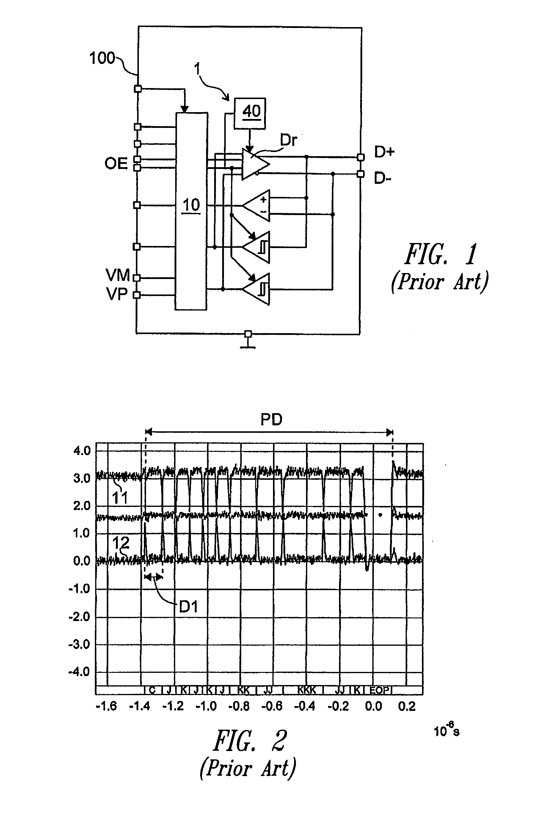
However, the activation of said bias circuit requires a certain time period and the data transmission may not start before the differential driver Dr is biased, therefore the transmission starts with a certain delay.
In some applications the delay between the enabling of the driver and the start of the data transmission may not allow an appropriate bias of the differential driver Dr.
In this case, the bias transistors of the Dr driver imply an anomaly in the transmission of the first bit of the packet of digital data to be transmitted, thus reducing the quality of the transmitted signal.

Method used


Image

  • Control device for a USB interface and control method thereof
  • Control device for a USB interface and control method thereof
  • Control device for a USB interface and control method thereof

Examples


Embodiment Construction

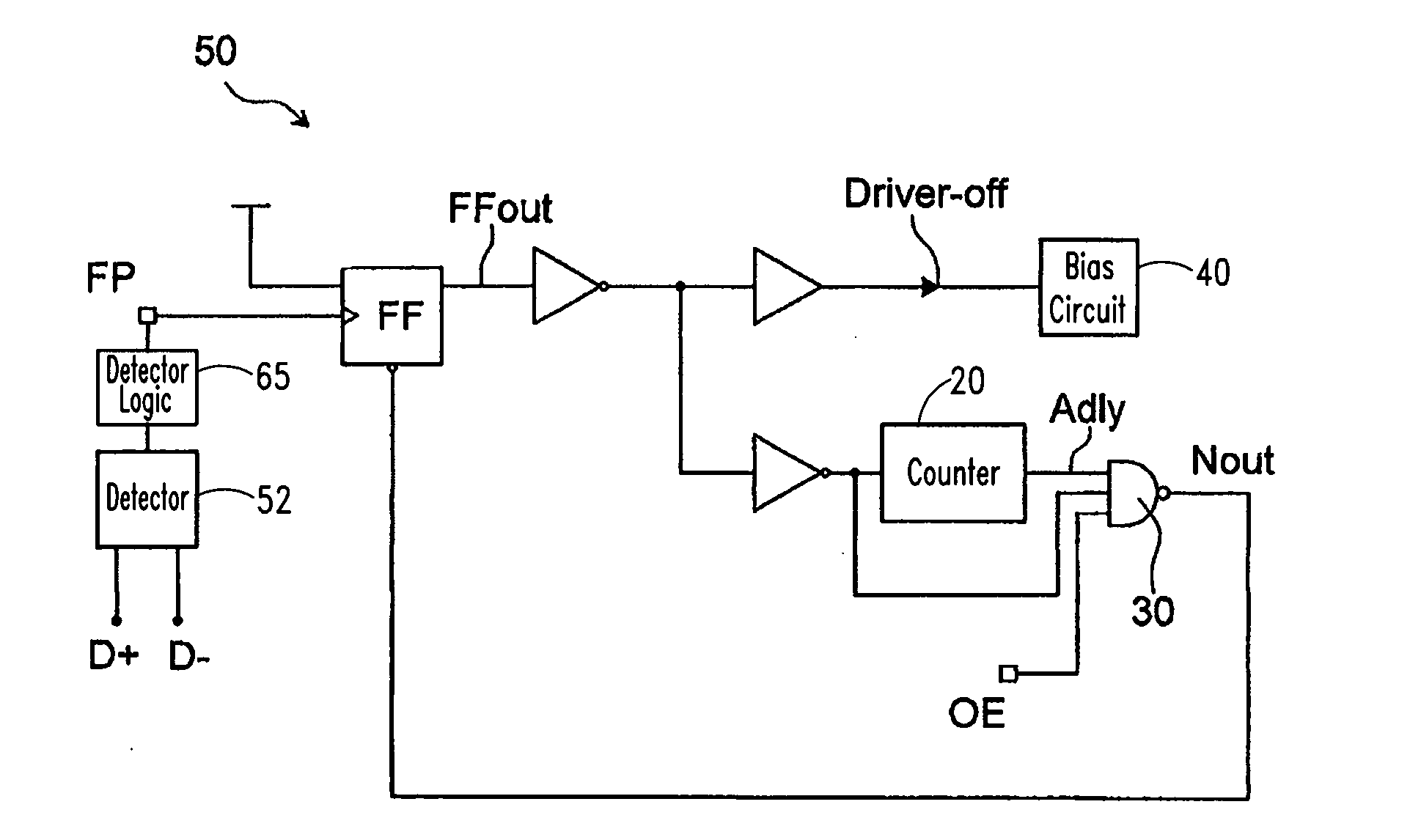
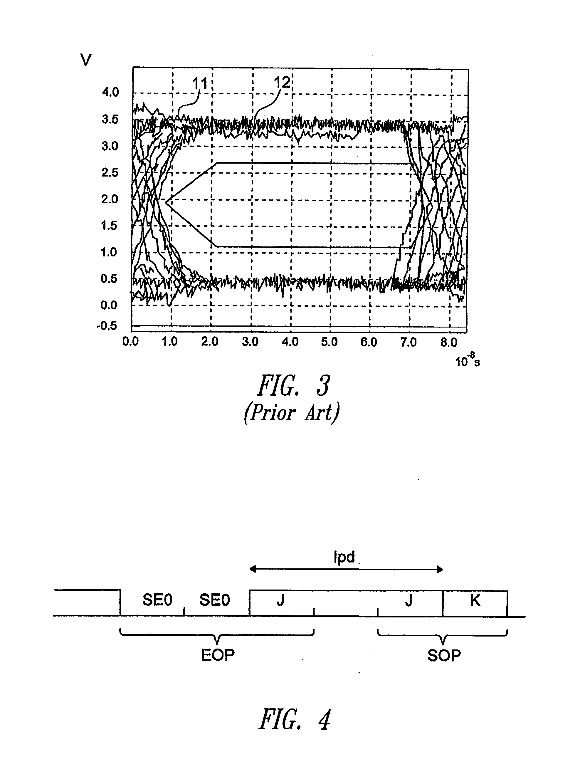
[0022]FIG. 4 shows the transmission of data packets according to one embodiment. Normally, a USB-type bus is based on a type of operation where a single device acts as a master and the other devices connected thereto act as slaves. In this manner the slave device is not allowed to start a communication unless the master device has not requested it; the sending of a data packet in the USB bus will immediately follow the switching in the transmission mode of a device. The method includes a prediction of the enabling of the differential drivers of the USB interface intended for the data transmission. Said method includes a step (FIG. 5) for identifying, on the USB bus, the end-of-packet signal EOP of a data packet which is transmitted along the USB bus. This may be detected by reception circuits for “single ended”-type signals of a USB interface 100′ (FIG. 9). A “single ended”-type signal consists of a Single Ended Zero (SEO) state for a time period of two bits followed by a transition...


PUM


Abstract

A control device for a USB interface including at least one first terminal for inputting the data to be transmitted and at least one second terminal for the transmission of the packet data on a bus; the packet data include one end-of-packet signal. The USB interface includes one circuit for the data transmission on said at least one second terminal; the USB interface is adapted to receive as an input a signal for the activation of the transmission circuit when data are received from the at least one first terminal and the transmission circuit includes a bias circuit. The control device includes a circuit for the detection of an end-of packet signal on said bus and a control circuit adapted to activate the bias circuit of the transmission circuit if said end-of-packet signal is detected by said detection circuit.

Description

CROSS-REFERENCE TO RELATED APPLICATION[0001]This application claims the benefit under 35 U.S.C. §119(a) of Italian Patent Application No. MI 2007A 001104 filed May 31, 2007, which is incorporated herein by reference in its entirety.BACKGROUND[0002]1. Technical Field[0003]The present invention relates to a control device for a Universal Serial Bus (USB) interface and to a control method thereof.[0004]2. Description of the Related Art[0005]USB interfaces allowing the transmission and reception of digital data are known in the state of the art; a typical USB interface is shown in FIG. 1. The interface includes two terminals, VM and VP, for inputting the data to be sent, the D+ and D− terminals for the data transmission and a terminal for inputting the OE signal to enable the data transmission; the USB interface includes a level shifter circuit 10 for shifting the level of the OE signal and of the data received on the VM and VP terminals, and driver circuitry 1 with drivers for the tran...

Claims


Application Information

Patent Timeline
IPC IPC(8): G06F1/12G06F13/00
CPCG06F13/385
Inventor MUSARRA, FEDERICOMARTINI, MARCO
Owner STMICROELECTRONICS SRL
Learn More