Light power adjusting method, optical transmitter, and optical receiver

a technology of light power and light power, which is applied in the direction of reflex reflectors, instruments, optical elements, etc., can solve the problems of deteriorating data transmission quality, difficult to accurately identify the optical fiber type, and difficult to accurately calculate the light power of only etc., to achieve rapid increase in the sbs-induced backward propagating light and high data transmission quality

Inactive Publication Date: 2008-01-29
FUJITSU LTD
View PDF3 Cites 5 Cited by
  • Summary
  • Abstract
  • Description
  • Claims
  • Application Information

AI Technical Summary

Benefits of technology

[0016]It is therefore an object of the present invention to provide a light power adjusting method, an optical transmitter, and an optical receiver suitable for ensuring high data transmission quality by preventing the rapid increase in SBS which occurs when the light power exceeds a predetermined value.
[0018]Accordingly, the incident light power with which the SBS-induced backward propagating light included in the reflected light returned from the optical transmission line rapidly increases, i.e., the light power threshold can be calculated. If the power of the light incident on the optical transmission line is set at a value equal to or smaller than the thus calculated light power threshold, the rapid increase in the SBS-induced backward propagating light, which is a nonlinear phenomenon of the optical fiber, can be prevented. Accordingly, high data transmission quality can be ensured.

Problems solved by technology

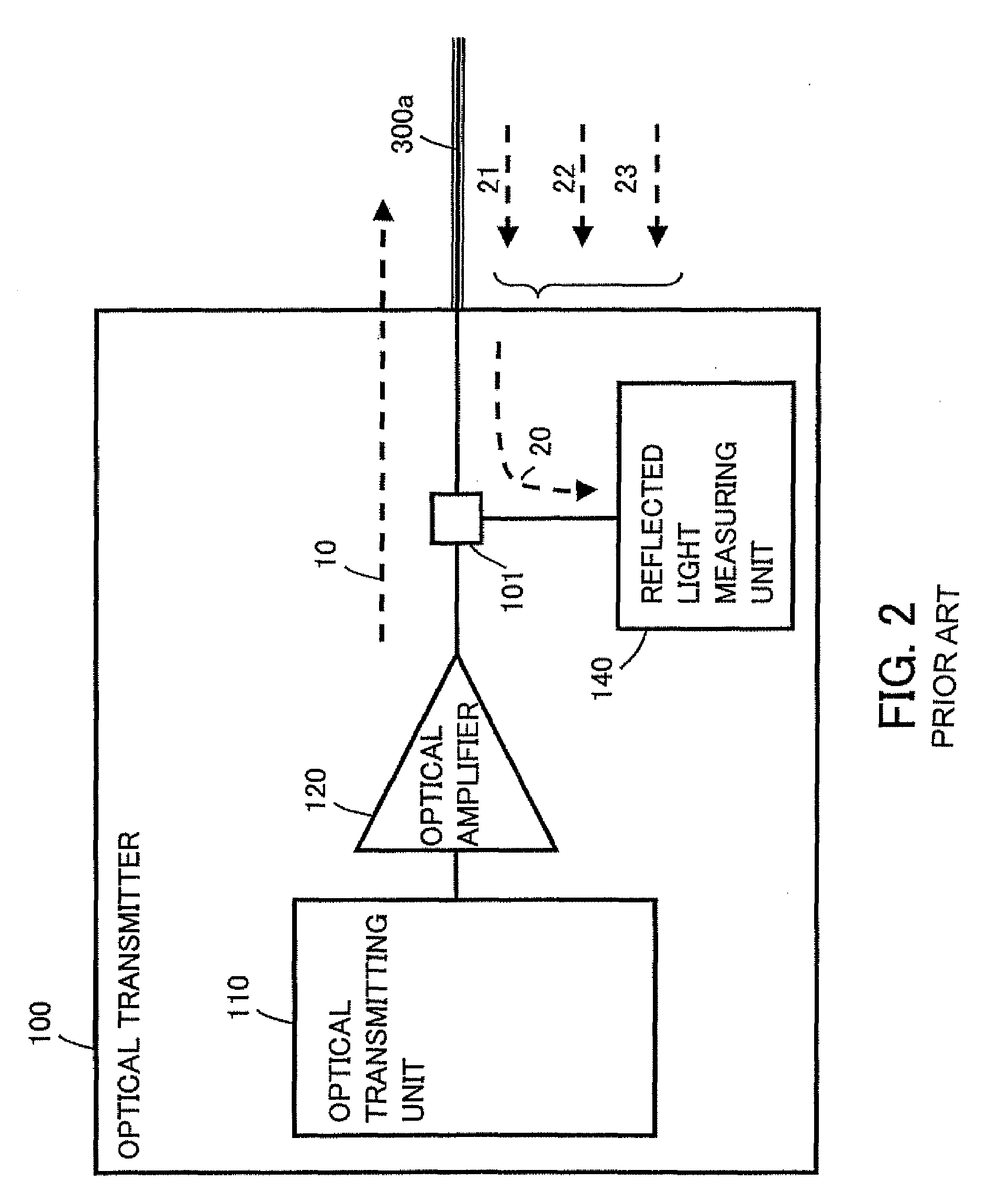
However, it is difficult to accurately calculate the light power of only the SBS-induced backward propagating light due to the influences of the Fresnel reflected light, the Rayleigh scattering light, and the like included in the reflected light.
It is thus difficult to accurately identify the optical fiber type.
This occurrence of the SBS-induced backward propagating light of a large amount forms a factor of the deterioration of the data transmission quality.

Method used


Image

  • Light power adjusting method, optical transmitter, and optical receiver
  • Light power adjusting method, optical transmitter, and optical receiver
  • Light power adjusting method, optical transmitter, and optical receiver

Examples


first embodiment

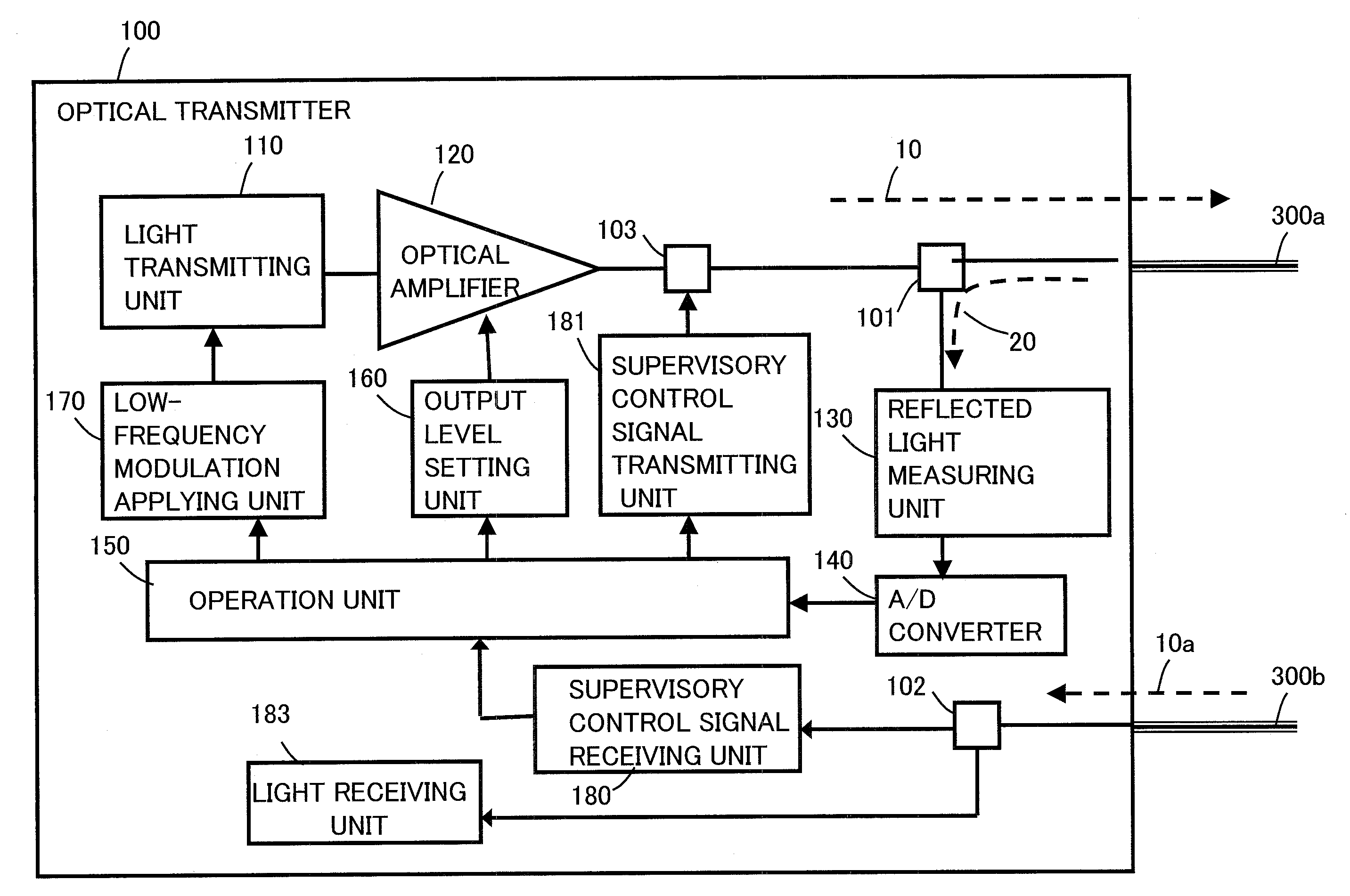
[0117]The flowchart of FIG. 10 illustrates the present invention in which the optical transmitter connected to the optical transmission line adjusts the power of the output light in cooperation with the optical receiver connected to the optical transmission line. Further, in the present embodiment, the optical receiver only sends the optical transmitter notification information notifying that the light reception level is insufficient and does not send information concerning an insufficient amount of the reception level.

[0118]The present operation includes the following steps.

[0119]At Step S01, the optical transmitter side sets the initial value of the frequency f of the low-frequency amplitude modulation to be applied at 0 Hz. That is, the frequency f is set not to apply the low-frequency amplitude modulation.

[0120]At Step S02, the optical transmitter side performs either one of the light power threshold calculation operations (1) and (2) illustrated in FIGS. 6 and 7, and the light ...

second embodiment

[0128]The flowchart of FIG. 11 illustrates the present invention in which the optical transmitter connected to the optical transmission line adjusts the power of the output light in cooperation with the optical receiver connected to the optical transmission line. Further, in the present embodiment, the optical transmitter side receives the information concerning the insufficient amount of the light reception level from the optical receiver side, and performs addition of appropriate power in accordance with the insufficient amount so that the optical receiver side can normally receive data. The present operation includes the following steps.

[0129]At Step S01, the optical transmitter side sets the initial value of the frequency f of the low-frequency amplitude modulation to be applied at 0 Hz. That is, the frequency f is set not to apply the low-frequency amplitude modulation.

[0130]At Step S02, the optical transmitter side performs either one of the light power threshold calculation o...


PUM

PropertyMeasurementUnit
incident light poweraaaaaaaaaa
poweraaaaaaaaaa
reflected light poweraaaaaaaaaa

Abstract

The present invention provides provide a light power adjusting method, an optical transmitter, and an optical receiver suitable for ensuring high data transmission quality by preventing the rapid increase in SBS which occurs when the light power exceeds a predetermined value.The incident light power with which the SBS-induced backward propagating light included in the reflected light returned from the optical transmission line rapidly increases, i.e., the light power threshold is calculated.By setting the power of the light incident on the optical transmission line at a value equal to or smaller than the thus calculated light power threshold, the rapid increase in the SBS-induced backward propagating light, which is a nonlinear phenomenon of the optical fiber, is prevented.

Description

BACKGROUND OF THE INVENTION[0001]1. Field of the Invention[0002]The present invention relates to a technique of adjusting light power incident on an optical transmission line, and more particularly to a light power adjusting method, an optical transmitter, and an optical receiver suitable for ensuring high data transmission quality by preventing a rapid increase in SBS (Stimulated Brillouin Scattering) which occurs when the light power exceeds a predetermined value.[0003]2. Description of the Related Art[0004]An SMF (Single Mode Fiber), which is one of optical fibers forming an optical transmission line, is divided into such types as SSMF (Standard SMF), DSF (Dispersion Shifted Fiber), NZ-DSF (Nonzero DSF), and so forth, depending on differences in a chromatic dispersion coefficient and an effective cross section area Aeff of a core.[0005]The optical fiber type is closely related to the power of the light incident on the optical fiber. Therefore, even if a certain incident light pow...

Claims


Application Information

Patent Timeline
Patent Type & Authority Patents(United States)
IPC IPC(8): G01N21/00H04B10/2507H04B10/071H04B10/077H04B10/2537H04B10/293H04B10/40H04B10/50H04B10/564H04B10/58H04B10/60
CPCH04B10/0775H04B10/0777H04B10/2537
Inventor OHTANI, TOSHIHIRO
Owner FUJITSU LTD
Why Eureka
Try Eureka