Optical transmission module

a transmission module and optical transmission technology, applied in the association of printed circuit parts, printed circuit non-printed electric components, coupling device connections, etc., can solve the problems of increasing manufacturing difficulty, circuits on flexible boards of two patents, fabrication and assembly difficulties, etc., to improve data transmission quality, reduce signal fidelity reduction, and high data rate optical transmission

Inactive Publication Date: 2006-04-04
IND TECH RES INST
View PDF2 Cites 5 Cited by
  • Summary
  • Abstract
  • Description
  • Claims
  • Application Information

AI Technical Summary

Benefits of technology

[0012]The object of the invention is to provide an optical transmission module that can prevent from signal fidelity reduction caused by photoelectric transformation through the transmission interface, and can improve the quality of data transmission. A flexible printed circuit board connects the photoelectric element and the main circuit board. The flexible printed circuit board includes grounding to prevent crosstalk and to prevent from problems of electromagnetic emission and interference.
[0013]The flexible printed circuit board and the coupling circuit effectively solve the problems of high data rate signal loss and mismatch between the photoelectric element and the circuit board. The flexible printed circuit board also solves the problem of connection stress between the circuit board and the photoelectric element and allows the bending based on mechanical design.
[0017]An optical transmission module according to the invention can reduce the signal fidelity reduction caused by photoelectric transformation through the transmission interface so as to improve the quality of data transmission. Through improvements of photoelectric elements, such as photoelectric elements packed by the currently most popular TOCAN (Transistor Outline CAN) method, and the interface between printed circuit boards, a high data rate optical transmission can be achieved without the need of expensive, bulky or new package methods.
[0018]Under considerations of fabricability and less cost increase, an optical transmission module of the invention can be well integrated with mechanical design to further improve the reliability. The module can solve the problems of electromagnetic emission and interference, signal crosstalk and so on, and enhance the performance of the whole module.

Problems solved by technology

For example, the multiple-layer flexible board used in U.S. Pat. No. 5,742,480 increases the manufacturing difficulty.
The circuits on the flexible board of the two patents are very complicated that make the fabrication and assembly difficult.
The connections between the optical members and the flexible printed circuit board require holes that easily cause signal distortion, parasitic effects and fail to achieve high data rate transmission.
Further, the bending of the flexible printed circuit board easily causes unreliable signal.
The connectors in this construction have problems of stress during connecting and decrease signal fidelity and cause interference to the receiver.
As described above, the optical transmission modules of prior arts have problems of lower signal fidelity and interference between transmitter and receiver.

Method used


Image

  • Optical transmission module
  • Optical transmission module
  • Optical transmission module

Examples


Embodiment Construction

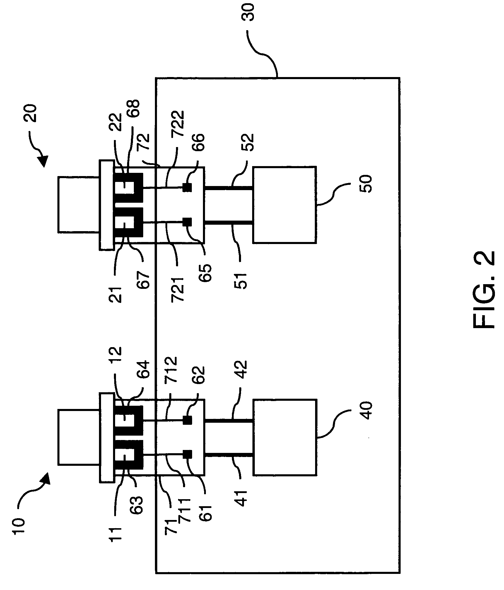
[0032]FIG. 2 shows a first embodiment of the invention. Two photoelectric elements 10 and 20 are used. One works as a transmitter and the other as a receiver; or all as transmitter or receiver. Of course, there can only be one photoelectric element.

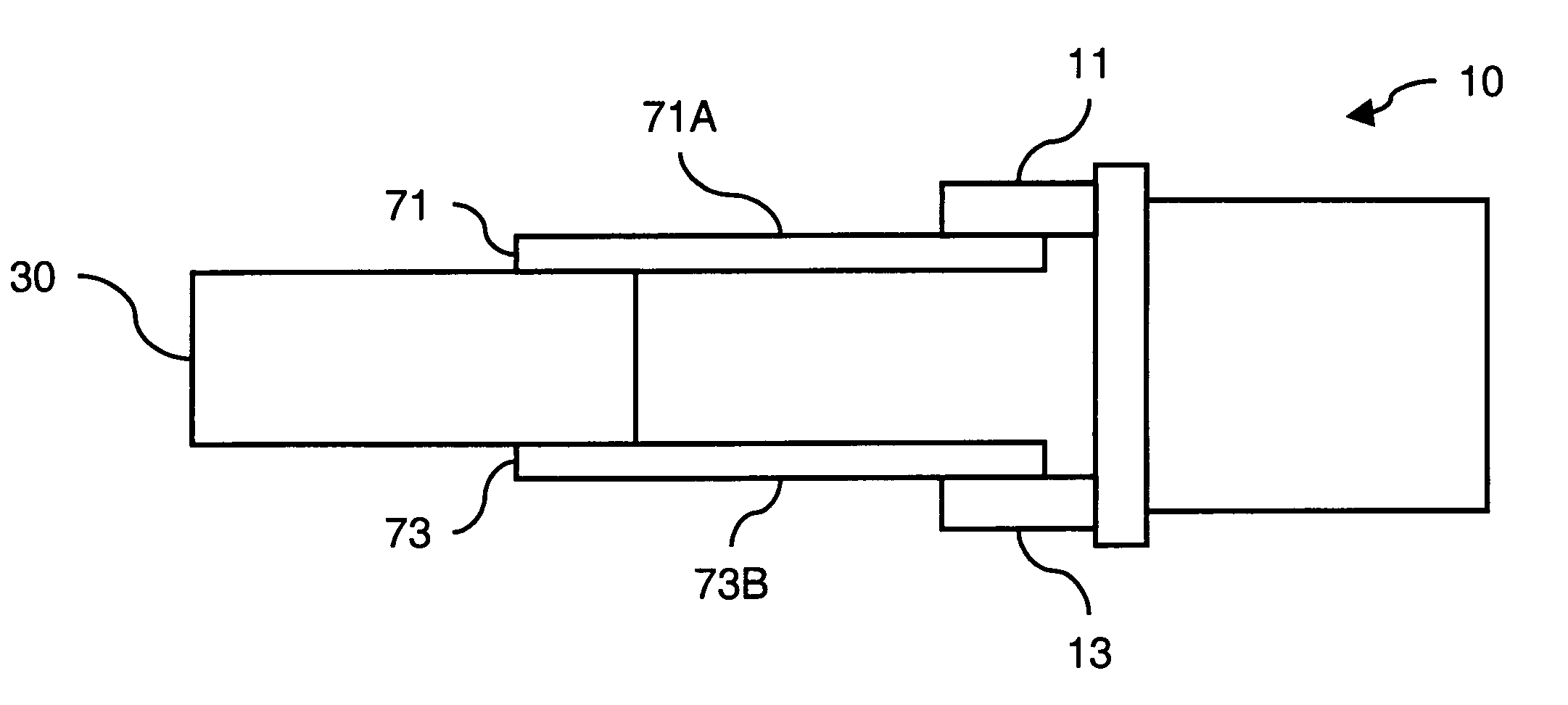
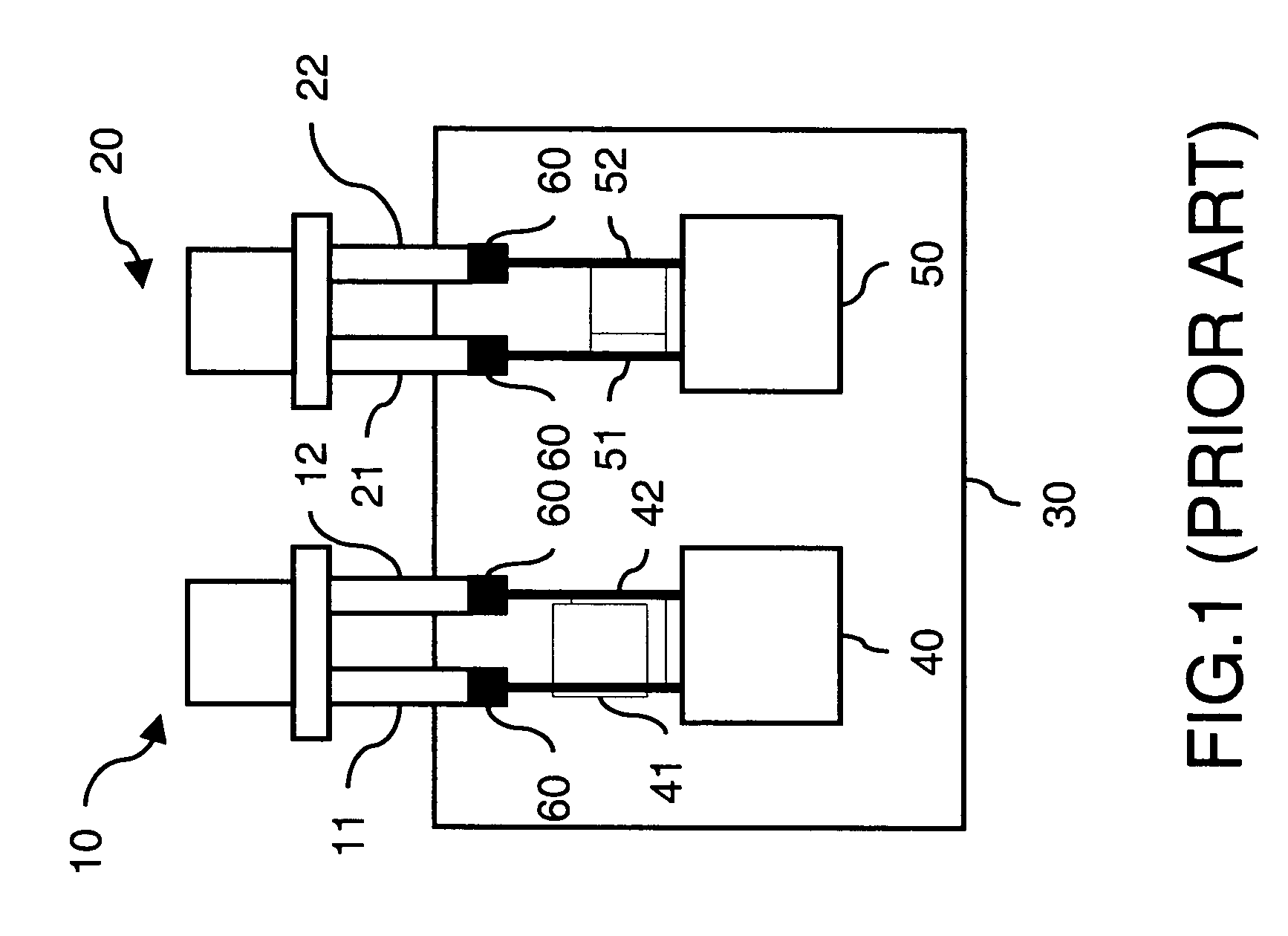
[0033]In the prior art, the pins of photoelectric elements are directly connected to printed circuit board. In the invention, the pins are electrically connected through an interface of flexible printed circuit board.

[0034]Pins of photoelectric element can be generally classified as signal pins and non-signal pins. The signal pins are for transmitting or receiving data. The non-signal pins are for power input or grounding.

[0035]For the photoelectric element 10, signal pins 11 and 12 are electrically connected to the flexible printed circuit board 71 via connecting points 63 and 64 respectively. A transmission line 711 connects the connecting point 63 and a connecting point 61. A transmission line 712 connects the connecting point 64 and a...


PUM


Abstract

An optical transmission module comprising at least a photoelectric element, a printed circuit board and a flexible printed circuit board is provided. The flexible printed circuit board electrically connects the photoelectrical elements and the printed circuit board. At least a ground plane is formed on the flexible printed circuit board to reduce crosstalk and electromagnetic interference. Transmission lines and impedance formed on the flexible printed circuit board solve the problems of signal distortion and impedance mismatch. The flexible printed circuit board also serves as a flexible interface to solve prior problems of connection stress between the photoelectric element and the printed circuit board.

Description

[0001]This Non-provisional application claims priority under 35 U.S.C. § 119(a) on patent Application No. 092129665 filed in Taiwan on Oct. 24, 2003, the entire contents of which are hereby incorporated by reference.BACKGROUND OF THE INVENTION[0002]1. Field of the Invention[0003]The invention generally relates to an optical transmission module, and in particular relates to an optical transmission module using a flexible printed circuit board as a connecting interface between the photoelectric element and the circuit board.[0004]2. Related Art[0005]In the field of optical data processing, optical transmitter / receiver transmits the data signal of processed information through an emitter into optical signal. The optical signal transferred through optical fiber to a remote photoelectric receiver where the optical signal is further converted into electrical signal so as to accomplish data communication.[0006]Some prior art optical data transmission modules are disclosed in patents such a...

Claims


Application Information

Patent Timeline
Patent Type & Authority Patents(United States)
IPC IPC(8): H01R12/00H05K1/00G02B6/42H05K1/14H05K1/18
CPCH05K1/147H05K1/145H05K2201/10121H05K1/189
Inventor KAO, MIN SHENGTSAI, CHENG HUNGCHIU, CHIA HUNGLEE, SHUN TIEN
Owner IND TECH RES INST
Why Eureka
Try Eureka