Cemented Open Hole Selective Fracing System

a selective fracing and open-hole technology, applied in the direction of fluid removal, borehole/well accessories, construction, etc., can solve the problems of hard to isolate that particular zone, damage to the formation, and difficult to restore and selectively produce certain portions of the zon

Inactive Publication Date: 2008-12-11
PEAK COMPLETION TECH
View PDF15 Cites 100 Cited by
  • Summary
  • Abstract
  • Description
  • Claims
  • Application Information

AI Technical Summary

Benefits of technology

[0014]It is another object of the present invention to provide a cemented open hole fracing system that may be selectively operated by selecting and opening certain stages to be fraced, but not other stages.
[0016]It is yet another object of the present invention to provide a cemented open hole fracing system that may be used in multi laterals with different valves being selectively operated so the production formation may be fraced in stages.

Problems solved by technology

One of the prior problems with earlier fracing methods is they require cementing of a casing in place and then perforating the casing at the producing zones.
The explosion used to perforate the casing can many times cause damage to the formation.
Plus, once the casing is perforated, then it becomes hard to isolate that particular zone and normally requires the use of packers both above and below the zone.
One of the problems with Wiemers is the fracing fluid is delivered over the entire production zone and you will not get concentrated pressures in preselected areas of the formation.
Once the pipe is perforated, it is very hard to restore and selectively produce certain portions of the zone and not produce other portions of the zone.
When fracing with sand, sand can accumulate and block flow.
Jones does not provide a method for alternately producing different zones or stages of a formation.
However, there are disadvantages to this particular method.
Also, the packers are expensive to run and set inside of the open hole in the formation.

Method used


Image

  • Cemented Open Hole Selective Fracing System
  • Cemented Open Hole Selective Fracing System
  • Cemented Open Hole Selective Fracing System

Examples


Embodiment Construction

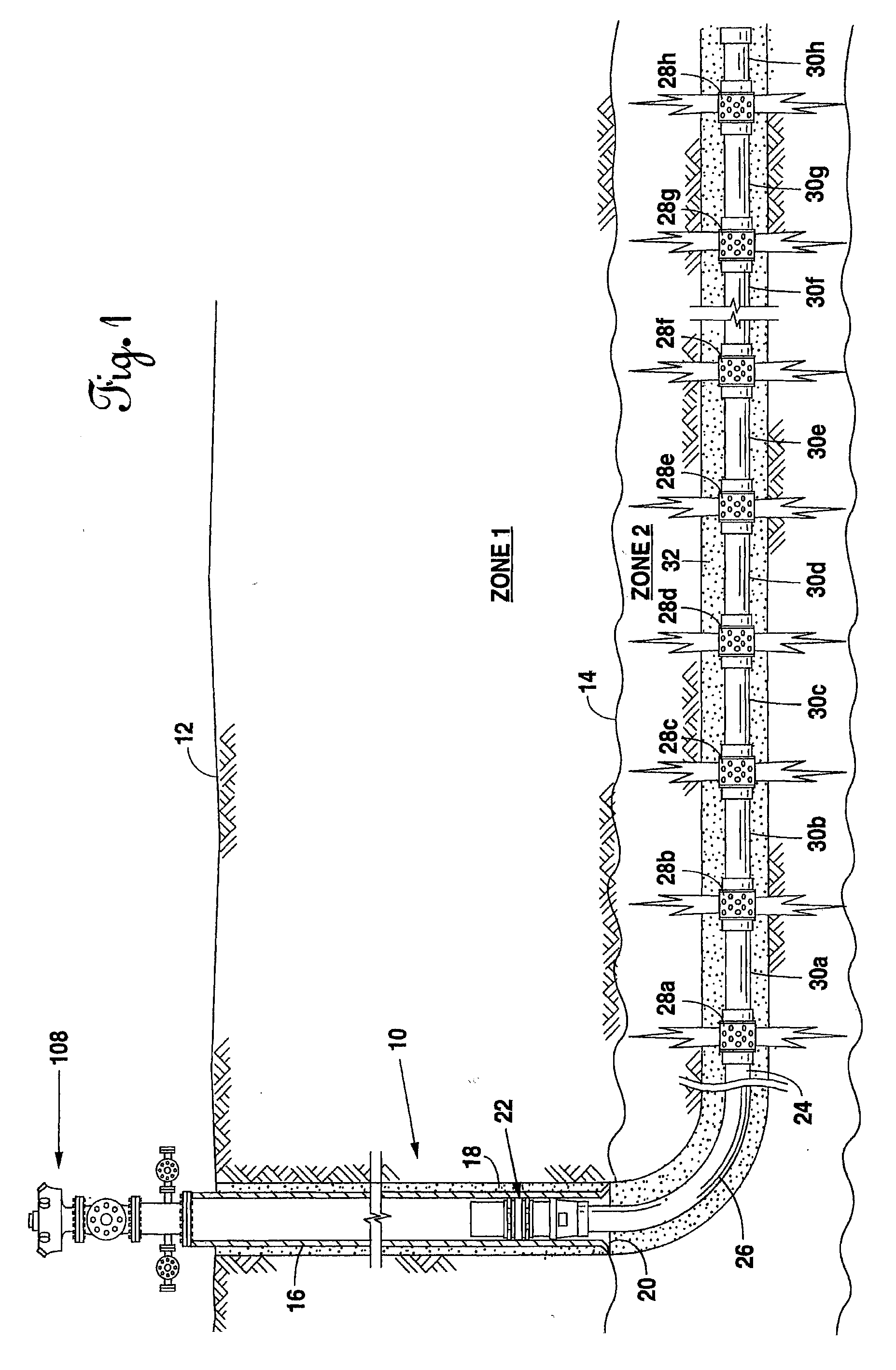
[0035]A cemented open hole selective fracing system is pictorially illustrated in FIG. 1. A production well 10 is drilled in the earth 12 to a hydrocarbon production zone 14. A casing 16 is held in place in the production well 10 by cement 18. At the lower end 20 of production casing 16 is located liner hanger 22. Liner hanger 22 may be either hydraulically or mechanically set.

[0036]Below liner hanger 22 extends production tubing 24. To extend laterally, the production well 10 and production tubing 24 bends around a radius 26. The radius 26 may vary from well to well and may be as small as thirty feet and as large as four hundred feet. The radius of the bend in production well 10 and production tubing 24 depends upon the formation and equipment used.

[0037]Inside of the hydrocarbon production zone 14, the production tubing 24 has a series of sliding valves pictorially illustrated as 28a thru 28h. The distance between the sliding valves 28a thru 28h may vary according to the preferenc...


PUM


Abstract

A cemented open hole selective fracing system and method are shown. In the producing zone, an open hole is drilled therein and a production tubing is cemented in place. At preselected locations along the production tubing, the production tubing will have sliding valves located there along. The sliding valves may be selectively opened, and the cement around the sliding valve dissolved. Thereafter, the formation may be fraced immediately adjacent the opened sliding valve. By selectively opening different combinations of sliding valves, fracing can occur in stages with more fracing pressure and more fracing fluid being delivered deeper into the formation. Just as the sliding valves can be selectively opened, the sliding valves can also be selectively closed to protect the production of the well.

Description

CROSS-REFERENCE TO RELATED APPLICATIONS[0001]This application claims the benefit of U.S. patent applications No. 11 / 079,950, filed Mar. 15, 2005, and No. 11 / 359,059, filed Feb. 22, 2006, which are incorporated herein by reference.BACKGROUND OF THE INVENTION[0002]1. Field of the Invention[0003]This invention relates to a system for fracing producing formations for the production of oil or gas and, more particularly, for fracing in a cemented open hole using sliding valves, which sliding valves may be selectively opened or closed according to the preference of the producer.[0004]2. Description of the Related Art[0005]Fracing is a method to stimulate a subterranean formation to increase the production of fluids, such as oil or natural gas. In hydraulic fracing, a fracing fluid is injected through a well bore into the formation at a pressure and flow rate at least sufficient to overcome the pressure of the reservoir and extend fractures into the formation. The fracing fluid may be of an...

Claims


Application Information

Patent Timeline
Patent Type & Authority Applications(United States)
IPC IPC(8): E21B34/06
CPCE21B43/00E21B43/11E21B43/12E21B43/26E21B2034/007E21B43/14E21B2200/06
Inventor HOFMAN, RAYMOND A.
Owner PEAK COMPLETION TECH
Why Eureka
Try Eureka