Aerial application dispersal system

a technology of aeroplanes and dispersal systems, applied in the field of aeroplanes, can solve the problems of increasing the headwind or drag of the aircraft, reducing the speed of the aircraft, and increasing the relative speed of the aircra

Inactive Publication Date: 2008-12-11
PETERSEN SCOTT
View PDF4 Cites 7 Cited by
  • Summary
  • Abstract
  • Description
  • Claims
  • Application Information

AI Technical Summary

Benefits of technology

[0007]The present invention is an aerial application dispersal system that comprises an aerial vehicle and an aerial dispersal unit. The aerial dispersal unit provides an insect control substance, a flake auger, and a motor to drive the flake auger for transporting the insect control substance to a dispensing chamber. The aerial dispersal unit also provides a glue substance, a pump, and a motor to drive the pump for transporting the glue substance from a storage container to the dispensing chamber for mixing with the insect control substance. The disp

Problems solved by technology

The inherent problem with this system is that the system does not account for wind turbulence or other forces that may affect the aircraft during application.
For example, these forces may increase the headwind or drag on the aircraft which would reduce the speed of the aircraft relative to the ground.
Or, these forces may increase the tailwind on the aircraft which would increase the speed of the aircraft relative to the ground.
This will cause an excess amount of the insect control substance to be dispensed over the designated area.
Likewise, if the aircraft is going faster than anticipated, this will cause a deficient amount of the insect control substance to be dispensed over the designated area.
As a result, by not taking into account the forces acting on the aircraft, the rippling effect is that the aerial dispensing apparatus is: (a) not able to provide a uniform disbursement or application of the insec

Method used


Image

  • Aerial application dispersal system
  • Aerial application dispersal system
  • Aerial application dispersal system

Examples


Embodiment Construction

will be better understood with reference to the following figures:

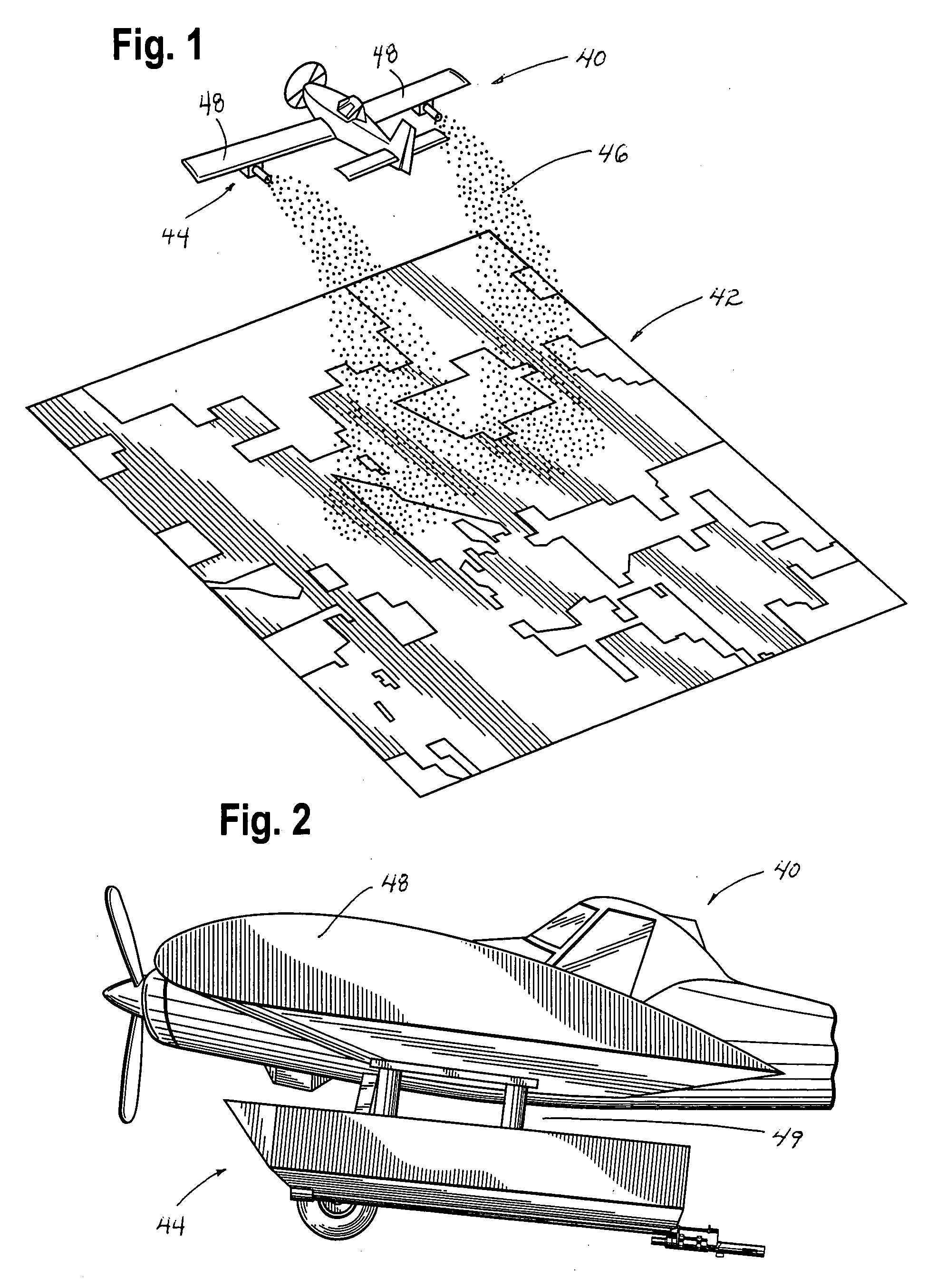
[0009]FIG. 1 is a perspective view of an aerial vehicle using Applicant's invention for dispensing an insect control substance over a designated area.

[0010]FIG. 2 is side perspective view of the aerial vehicle and, in particular, illustrating the attachment of the aerial dispersal unit to the aerial vehicle.

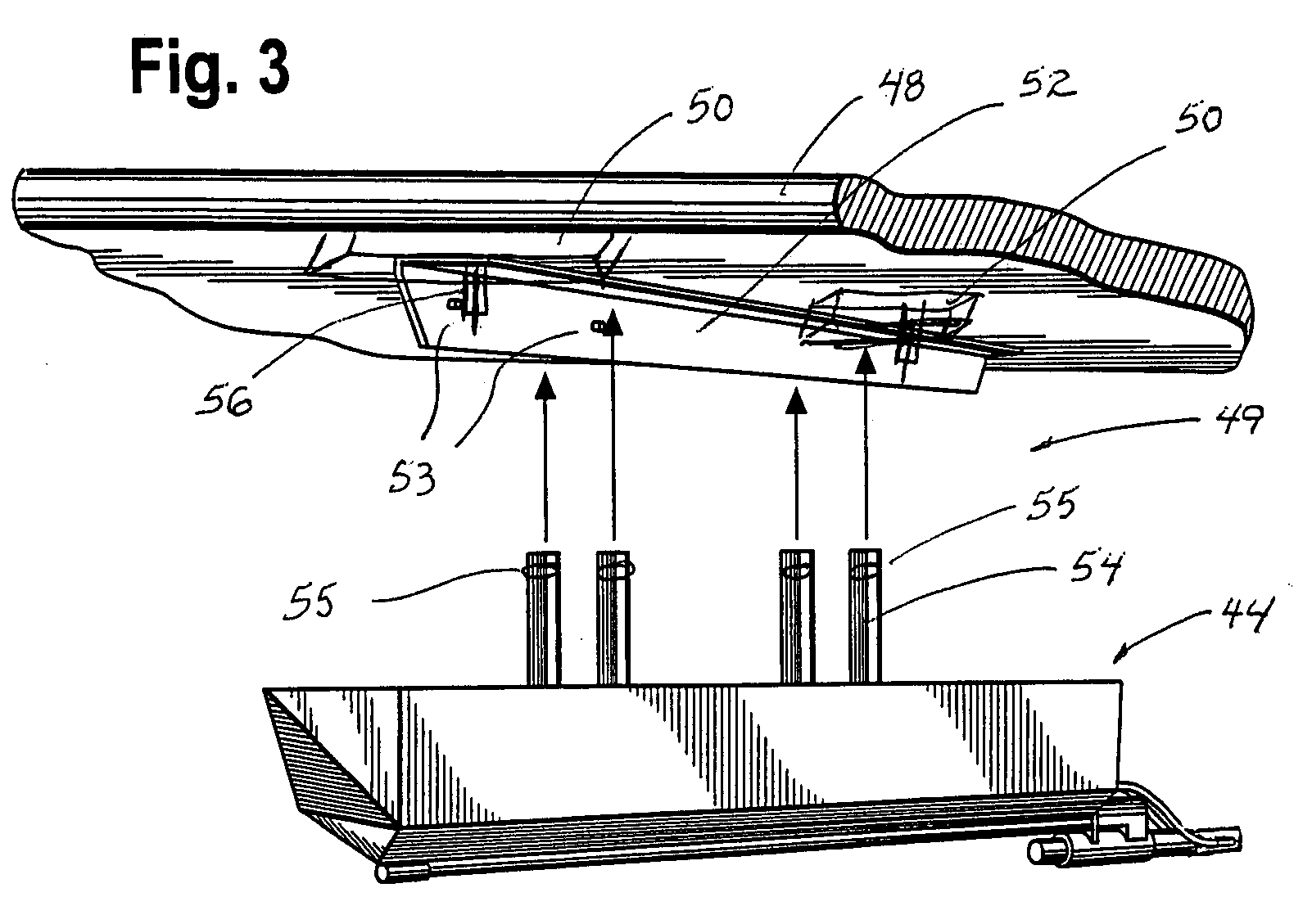
[0011]FIG. 3 is a perspective view, with portions removed, illustrating the aerial dispersal unit as detached from the aerial vehicle.

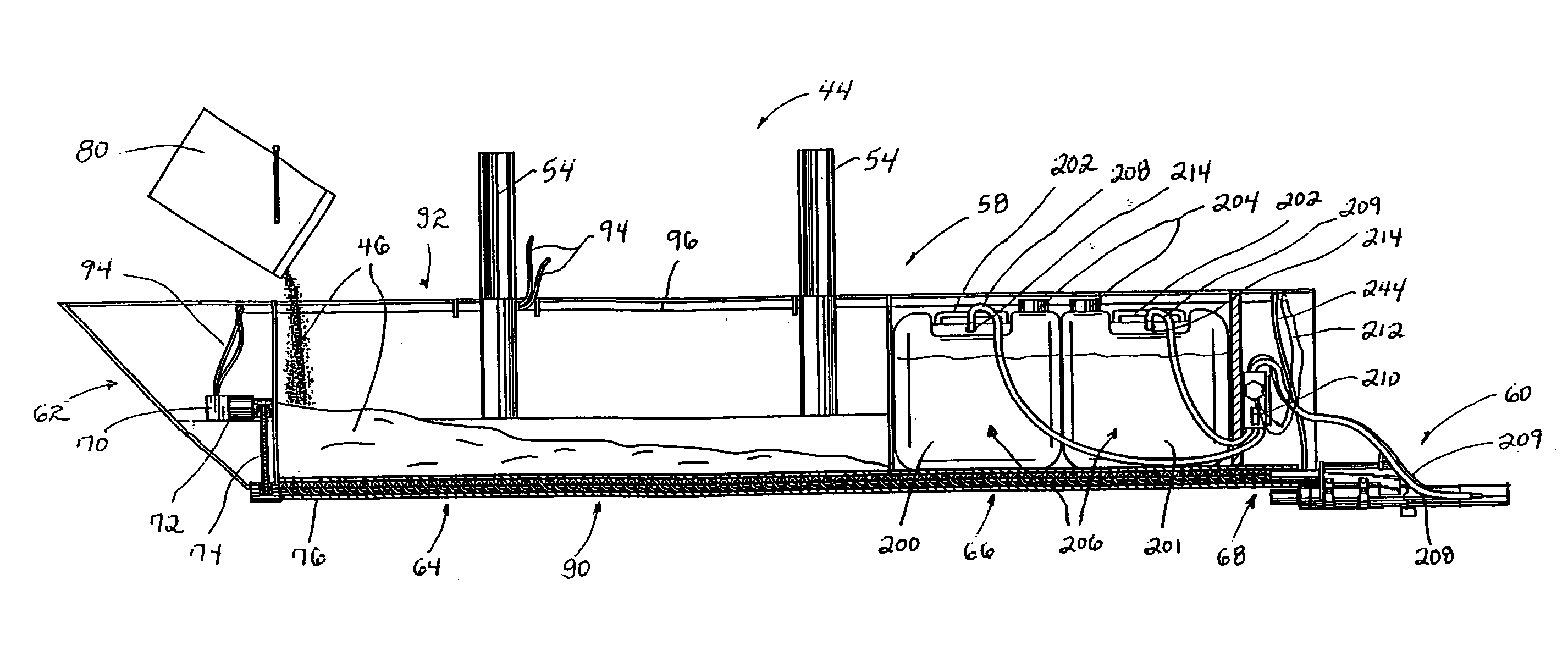
[0012]FIG. 4 is a side perspective view, with portions removed, illustrating the aerial dispersal unit.

[0013]FIG. 5 is a top perspective view of the aerial dispersal unit.

[0014]FIG. 6 is an end perspective view of the aerial dispersal unit and, in particular, illustrating the system for transporting the glue substance from the containers to the dispensing chamber.

[0015]FIG. 7 is a side perspective view of the dispensing chamber in the locked position.

[0016]FIG. 8 is a side perspectiv...


PUM


Abstract

An aerial application dispersal system that comprises an aerial vehicle and an aerial dispersal unit. The aerial dispersal unit provides an insect control substance, a flake auger, and a motor to drive the flake auger for transporting the insect control substance to a dispensing chamber. The aerial dispersal unit also provides a glue substance, a pump, and a motor to drive the pump for transporting the glue substance from a storage container to the dispensing chamber for mixing with the insect control substance. The dispensing chamber is provided with a motor for forcing the insect control substance mixed with the glue substance out an exit portal for disbursement over the designated area. A control box, control switches, global positioning satellite system, and dispersal unit operator interface are also provided for automatically regulating the mixing and dispensing rate of the insect control substance and glue substance in relation to the ground speed of the aerial vehicle for maintaining a constant, uniform disbursement of a bonded substance over a designated area.

Description

I. FIELD OF THE INVENTION[0001]The present invention relates to an aerial application dispersal system attached to an aerial vehicle such as an aircraft for dispensing an insect control substance. More specifically, the aerial application dispersal system continually monitors and regulates the dispensing rate of the insect control substance in relation to the ground speed of the aerial vehicle for maintaining a constant, uniform disbursement of the insect control substance during application.II. DESCRIPTION OF THE PRIOR ART[0002]The application of insect control substances to crops, fields, or other areas is proving a successful means to protect designated areas against insect damage. In a typical application, flakes imbedded with a chemical substance such as pheromone are disbursed from the aerial dispersal system over the designated area to be protected during the insect mating season. Upon application to the designated area, the pheromones are naturally released from the flakes t...

Claims


Application Information

Patent Timeline
IPC IPC(8): B64D1/18
CPCA62C3/0242B64D1/18
Inventor PETERSEN, SCOTT
Owner PETERSEN SCOTT
Why Eureka
Try Eureka