Photoelectric encoder

a technology of photoelectric encoder and encoder, which is applied in the direction of optical conversion of sensor output, instruments, measurement devices, etc., can solve the problems of signal strength decline, and achieve the effects of small image formation effect, improved reliability of scale dirt, and stabilized signal strength

Active Publication Date: 2008-12-11
MITUTOYO CORP
View PDF1 Cites 1 Cited by
  • Summary
  • Abstract
  • Description
  • Claims
  • Application Information

AI Technical Summary

Benefits of technology

[0011]It is therefore an object of the invention to improve reliability for scale dirt, stabilize the signal strength, and improve the signal detection efficiency.
[0014]The surface of the transparent protective material can have hydrophilicity or lipophilicity by using an oxide such as a titanium oxide, a titanium dioxide or the like. More specifically, the surface of the transparent protective material may be covered by a titanium oxide film or the transparent protective material may be made of a titanium oxide, so that the transparent protective material can have hydrophilicity. The surface of the transparent protective material may be covered by a titanium dioxide film or the transparent protective material may be made of a titanium dioxide, so that the transparent protective material can have lipophilicity. In an environment in which water is used, the transparent protective material has hydrophilicity, so that it is possible to prevent the water droplet from forming on the transparent protective material or the water from being accumulated on the transparent protective material because the water spreads on the transparent protective material. In an environment in which oil is used as in a machine tool, the transparent protective material has lipophilicity, so that it is possible to prevent the oil droplet from forming on the transparent protective material or the oil from being accumulated on the transparent protective material because the oil spreads on the transparent protective material. Therefore, it is possible to prevent the optical influence by the water droplet or oil droplet from occurring.
[0017]According to the invention, the transparent protective material has the thickness equal to or greater than the depth of focus (DOF) of the image forming optical system and thus the effect on image formation is small. Therefore, reliability for scale dirt is improved, the signal strength is stabilized, and the signal detection efficiency is improved. Moreover, the dirt portion spreads on he transparent protective material by means of the transparent protective material having hydrophilicity or lipophilicity, for example, the refractive power caused by the scale dirt lessens, and the interference fringe scarcely changes. Therefore, reliability for scale dirt is further improved, the signal strength is further stabilized, and the signal detection efficiency is further improved.

Problems solved by technology

However, the transmission type and the reflection type have a problem of a decrease in the signal strength if dirt exists on the scale surface.

Method used


Image

  • Photoelectric encoder
  • Photoelectric encoder
  • Photoelectric encoder

Examples


first embodiment

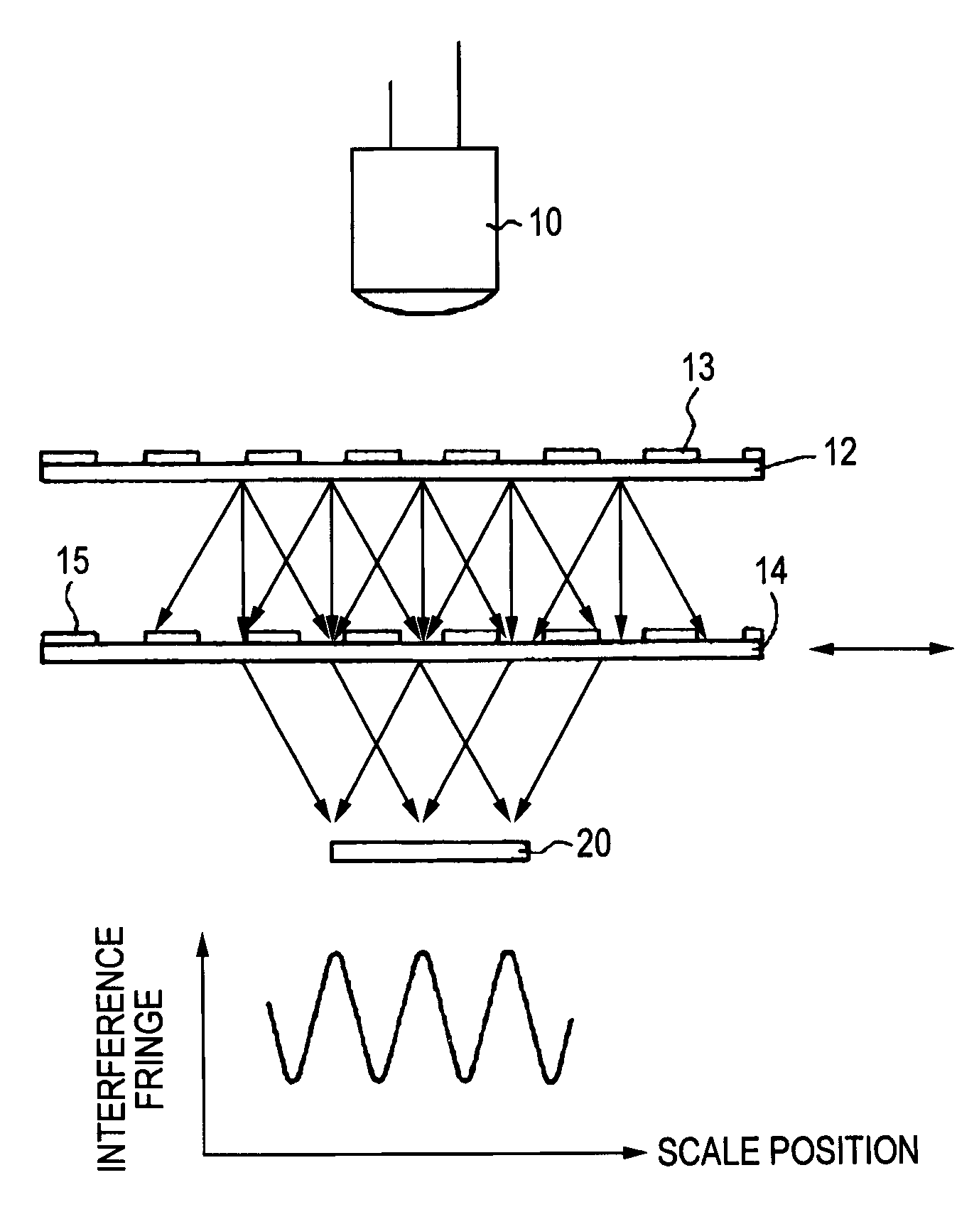
[0033]FIG. 8 shows the invention applied to a transmission encoder like that in FIG. 1 having an image forming optical system made of a lens 22. As shown in FIG. 8, a transparent protective material 40 or 42 is disposed on a grating 15 side surface of a scale 14, whereby dirt S is deposited on the transparent protective material 40 or 42 rather than on the grating 15 face of the scale 14 and the dirt portion spreads because of hydrophilicity or lipophilicity. Therefore, the refractive power lessens and an interference fringe scarcely changes. Further, the thickness t of the transparent protective material 40 or 42 is larger than the DOF and thus the effect on image formation through the lens 22 is small.

[0034]Particularly, if an aperture 24 is added to the focal position of the lens 22 as indicated by the dashed line in the figure, the DOF lessens, so that the thickness t of the transparent protective material 40 or 42 can be thinned.

second embodiment

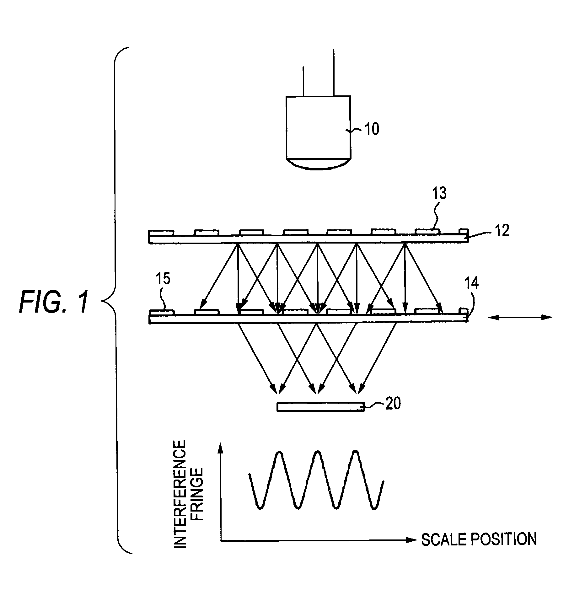
[0035]Next, FIG. 9 shows the invention applied to a reflection encoder as shown in FIG. 2.

[0036]Also in the embodiment, dirt S spreads on a transparent protective material 40 or 42 and thus the refractive power lessens and an interference fringe scarcely changes. Further, thickness t of the transparent protective material 40 or 42 is larger than the DOF and thus the effect on image formation through a lens 22 is small.

third embodiment

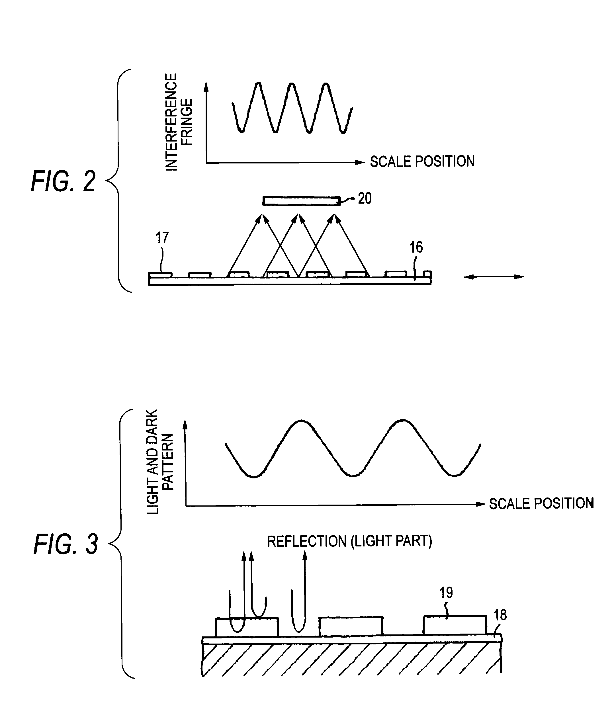
[0037]Next, FIG. 10 shows the invention applied to a reflection encoder as shown in FIG. 3.

[0038]Also in the embodiment, the portion of dirt S spreads and thus an interference fringe scarcely changes. Further, thickness t of a transparent protective material 40 or 42 is larger than the DOF and thus the effect on image formation through a lens 22 is small.

[0039]The transparent protective material can be implemented as a band-pass filter formed by multilayer coating by evaporation, for example, and can be provided with a function of removing external visible light, etc., for example, when an infrared light source is used.

[0040]Further, in the reflection encoder as shown in FIGS. 2 and 3, as with the first embodiment of FIG. 1, the aperture 24 may be added to the focal position of the lens 22, and in this case, since DOF lessens, the thickness t of the transparent protective material 40 or 42 can be thinned.


PUM


Abstract

In a photoelectric encoder including a scale (14, 16, 18) for making a relative move and an image forming optical system (22, 24), adapted to detect relative displacement of the scale, a transparent protective material (40, 42) having a thickness t equal to or greater than the depth of focus (DOF) of the image forming optical system is disposed on the lattice (15, 17, 19) side surface of the scale. The transparent protective material can be transparent tape 40 bonded to the lattice side surface of the scale or a transparent protective material 42 applied to the lattice side surface of the scale. The surface of the transparent protective material can have hydrophilicity or lipophilicity.

Description

TECHNICAL FIELD[0001]The present invention relates to a photoelectric encoder and in particular to a photoelectric encoder capable of improving reliability for scale dirt, stabilizing the signal strength, and improving the signal detection efficiency, suited for use as a photoelectric encoder including a scale having an optical grating and an image forming optical system which can move relatively to the scale, adapted to detect relative displacement of the scale using interference of light.RELATED ART[0002]A photoelectric encoder of grating interference type for detecting relative displacement of a scale using interference of light is known as described in patent documents 1 to 3.[0003]If the photoelectric encoder of grating interference type is of transmission type, light projected onto an index scale 12 from a light source 10 and diffracted on a grating 13 is again diffracted on a grating 15 on a main scale (simply, referred as scale) 14 to produce a light and dark interference fr...

Claims


Application Information

Patent Timeline
Patent Type & Authority Applications(United States)
IPC IPC(8): G01D5/36G01D5/34
CPCG01D5/347
Inventor MIZUTANI, MIYAKO
Owner MITUTOYO CORP
Why Eureka
Try Eureka