Inputs switching device

a switching device and input technology, applied in the field of input switching devices, can solve problems such as difficulty in setting external inputs according to the frequency of us

Inactive Publication Date: 2008-12-11
FUNAI ELECTRIC CO LTD
View PDF7 Cites 9 Cited by
  • Summary
  • Abstract
  • Description
  • Claims
  • Application Information

AI Technical Summary

Problems solved by technology

That is, it is difficult to set external inputs according to the frequency of use and / or preference of the user.

Method used


Image

  • Inputs switching device
  • Inputs switching device
  • Inputs switching device

Examples


embodiment 1

B. Embodiment 1

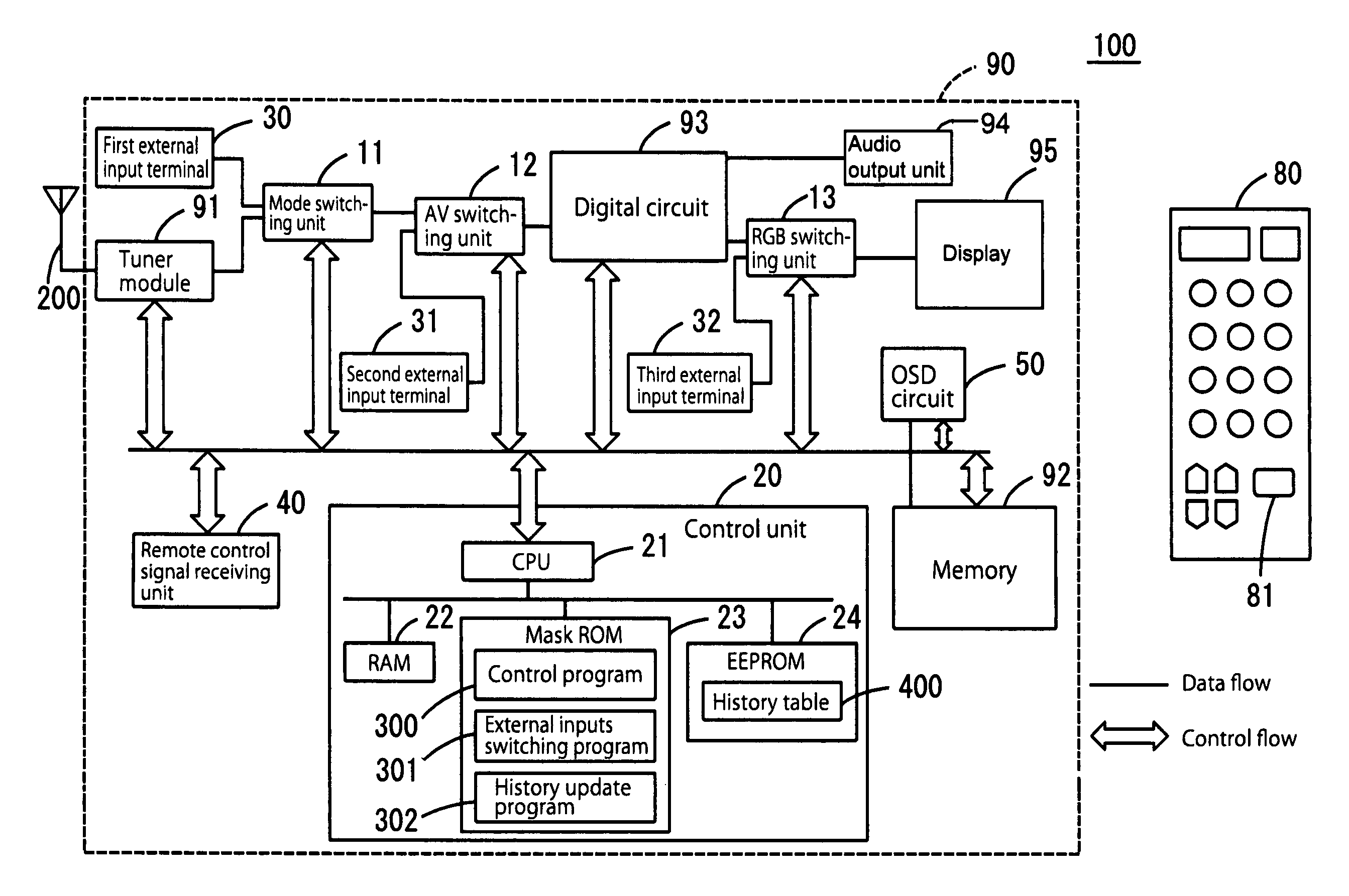
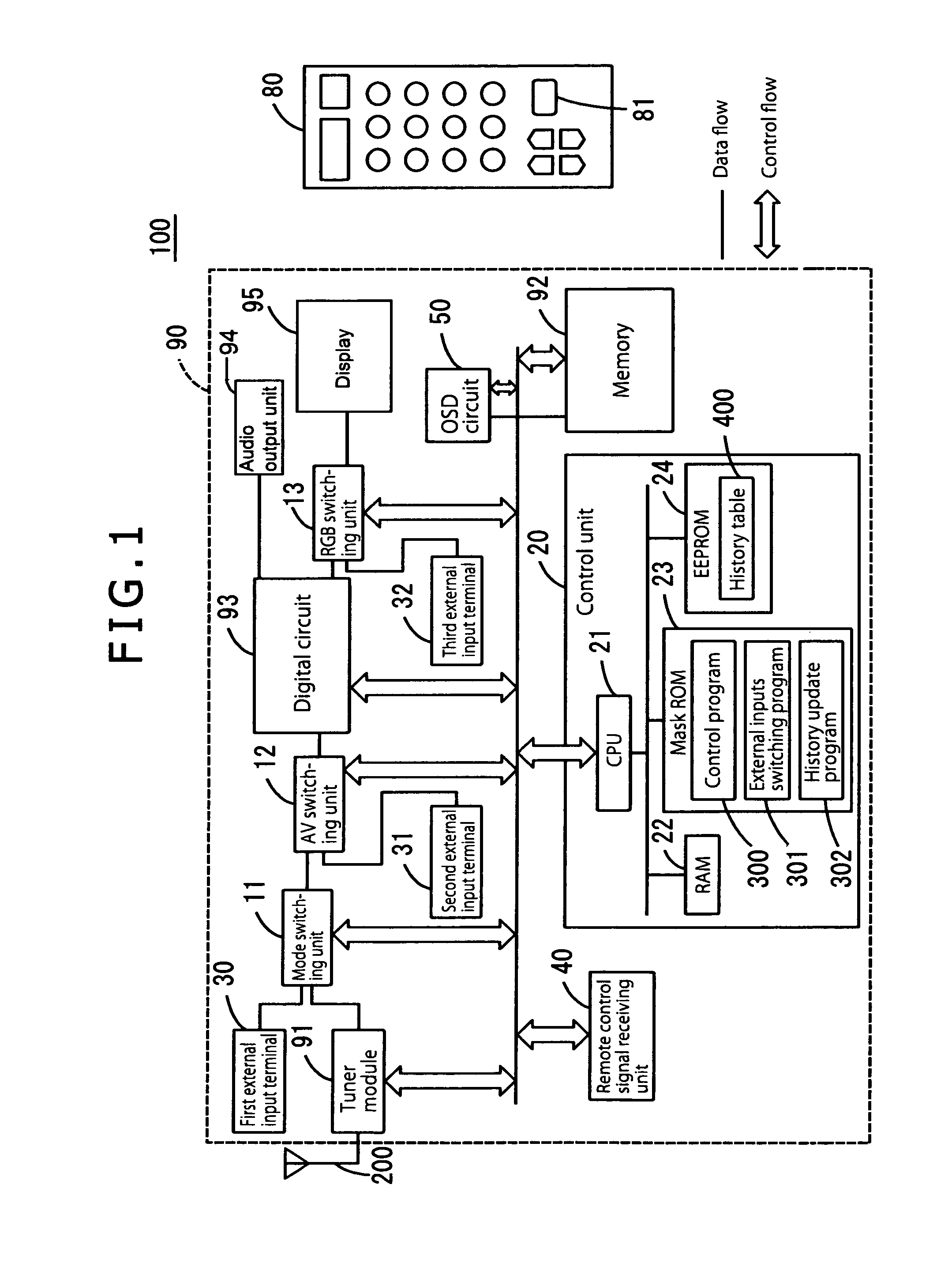
[0037]An embodiment using the television receiver 100 will be described below. In this embodiment, the user sets in advance external inputs to be selected by pressing the external inputs switching key 81. Accordingly, when the user operates the external inputs switching key 81, only the preset external input is selected in response to the pressing of each key This displays the selected external input on the screen.

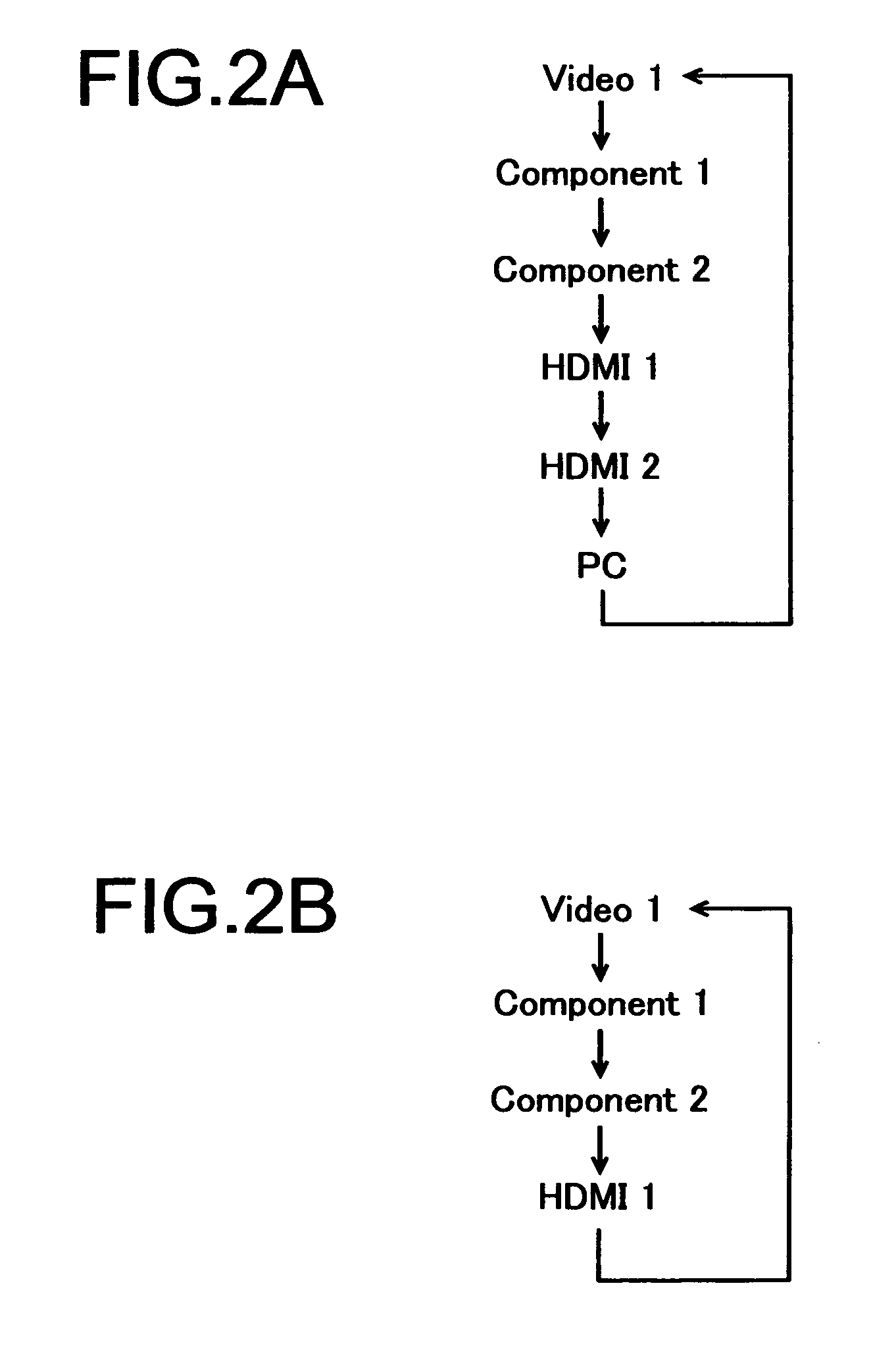
[0038]The television receiver 100 is, as shown in FIG. 2(a), capable of switching external inputs: VIDEO 1, VIDEO 2, Component 1, Component 2, HDMI 1, HDMI 12, and PC. In order to switch to VIDEO 1, VIDEO 2, Component 1, Component 2, and HDMI 1 in this order as shown in FIG. 2(b), the user sets the television receiver 100 using the following procedure. First, the user displays a menu screen on the screen of the receiver 90 by operating, for example, the remote control 80. Then on the menu screen, the user displays a screen based on the database stored in the...

embodiment 2

C. Embodiment 2

[0039]Another embodiment using the television receiver 100 will be described below. In this embodiment, the database the CPU 21 refers to is automatically updated each time an external input is used. The database history to be updated is, for example, the frequency of use or operating time of an external input. Based on the updated database, the CPU 21 changes an external input to be switched. Thereafter, when the external inputs switching key 81 is pressed, the CPU 21 switches external inputs based on the updated database.

[0040]In the EEPROM 24 according to the present invention, a history table as shown in FIG. 4 is stored. The history table contains code numbers indicating the order of selection of external inputs, the name of respective external inputs, and the selection frequency and execution time of an external input as the history information to be updated. When an external input is selected, the CPU 21 updates the history table according to the history update...


PUM


Abstract

The present invention discloses an inputs switching device, includes: a plurality of external inputs accepting unit to accept different external inputs; a switching order storage unit to store a switching order of the external inputs to be output; an external inputs switching unit to switch the external inputs to be output sequentially as set forth within the stored switching order in response to a pressing of an operation key; and a non-switching unit to make the external inputs switching unit not to switch a specified external input that is specified from the external inputs of the switching order.

Description

CROSS-REFERENCES TO RELATED APPLICATIONS[0001]The present application is related to the Japanese Patent Application No. 2007-149025, filed Jun. 5, 2007, the entire disclosure of which is expressly incorporated by reference herein.BACKGROUND OF THE INVENTION[0002](1) Field of the Invention[0003]The present invention relates to an inputs switching device capable of switching a plurality of external inputs, and more specifically to an inputs switching device capable of switching external inputs by simple operation of an operation key.[0004](2) Description of the Related Art[0005]An inputs switching device is a device to switch inputs from a plurality of external inputs connected thereto and output them. The inputs switching device is, for example, mounted in a television receiver and switches the signals input from external apparatuses to output them selectively. The inputs switching device includes: an interface that accepts external inputs; a switching means that switches the externa...

Claims


Application Information

Patent Timeline
Patent Type & Authority Applications(United States)
IPC IPC(8): H04N5/44H04N7/173
CPCH04N5/765H04N5/775H04N21/436
Inventor SHIOJI, TOMONORI
Owner FUNAI ELECTRIC CO LTD
Why Eureka
Try Eureka