Microphone with Aligned Apertures

a microphone and aperture technology, applied in the field of microphones, can solve the problems of difficult to set the low frequency cutoff, and insufficient control of the gap size,

Active Publication Date: 2008-12-11
INVENSENSE
View PDF11 Cites 66 Cited by
  • Summary
  • Abstract
  • Description
  • Claims
  • Application Information

AI Technical Summary

Problems solved by technology

Undesirably, setting the low frequency cutoff can be difficult due to such high resistance.
Such a method, however, has drawbacks.
Among other things, it dictates the gap size in a manner that may interfere with other design considerations.
In addition, controlling the gap size often does not sufficiently address the above noted air resistance problem, in which the backplate aperture is directly under a solid portion of the diaphragm.

Method used


Image

  • Microphone with Aligned Apertures
  • Microphone with Aligned Apertures
  • Microphone with Aligned Apertures

Examples


Embodiment Construction

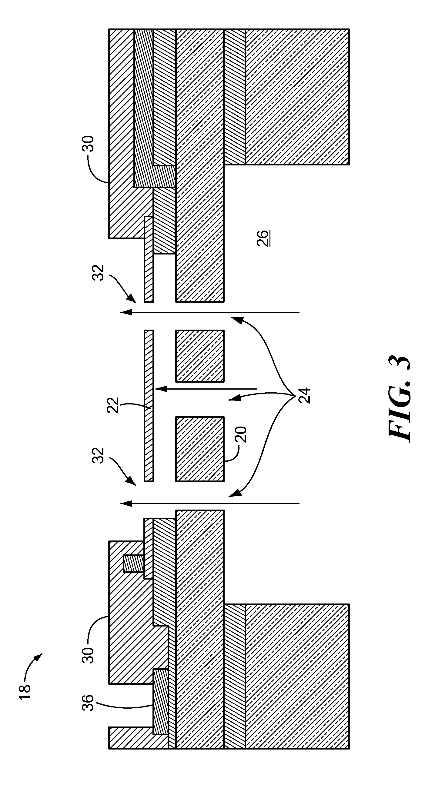
[0023]In illustrative embodiments, the diaphragm and backplate of a MEMS microphone cooperate to reduce air resistance through the microphone. As a result, the microphone can be more easily tuned to a precise low frequency cutoff point. Details of illustrative embodiments are discussed below.

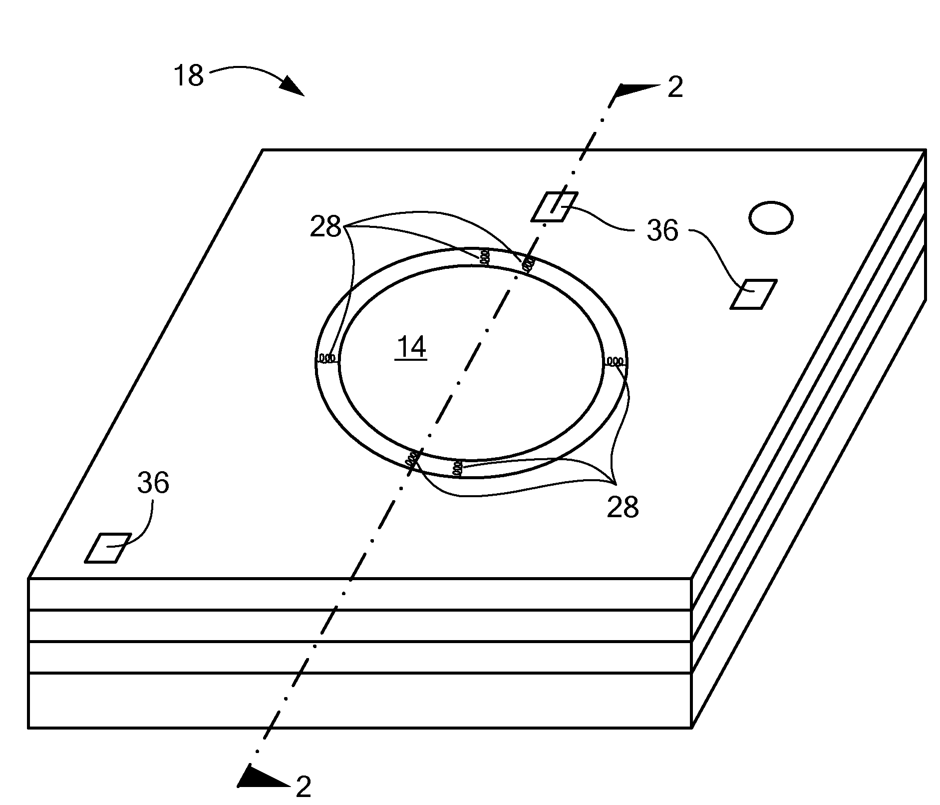
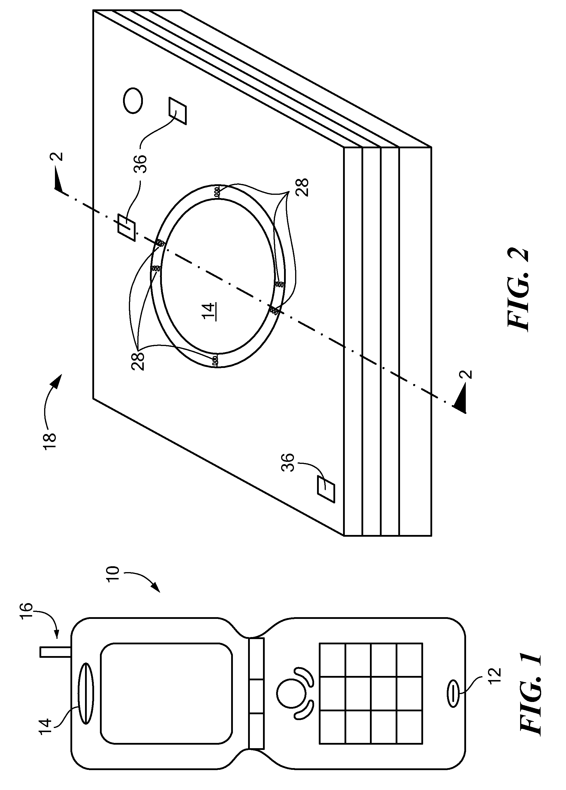
[0024]FIG. 1 schematically shows a mobile telephone 10 that can use a microphone configured in accordance with illustrative embodiments. In simplified terms, the telephone 10 has a receiver 12 for receiving an audio signal (e.g., a person's voice), a speaker portion 14 for generating audio signals, and a transponder 16 for transmitting and receiving electromagnetic signals encoding audio signals. During use, a person may speak into the receiver 12, which has a microphone (FIG. 2, discussed below) that converts the person's voice into an electrical signal. Internal logic (not shown) and the transponder 16 modulate this signal to a remote source, such as to a satellite tower and, ultimately, to an...


PUM

PropertyMeasurementUnit
frequencyaaaaaaaaaa
frequencyaaaaaaaaaa
frequencyaaaaaaaaaa

Abstract

A MEMS microphone has a backplate with a given backplate aperture, and a diaphragm having a diaphragm aperture. The given backplate aperture is substantially aligned with the diaphragm aperture.

Description

PRIORITY[0001]This patent application claims priority from provisional U.S. patent application No. 60 / 942,315, filed Jun. 6, 2007, entitled, “MICROPHONE WITH ALIGNED APERTURES,” attorney docket number 2550 / B56, and naming Eric Langlois, Thomas Chen, Xin Zhang, and Kieran Harney as joint inventors, the disclosure of which is incorporated herein, in its entirety, by reference.FIELD OF THE INVENTION[0002]The invention generally relates to microphones and, more particularly, the invention relates to controlling the low frequency cutoff point for microphone.BACKGROUND OF THE INVENTION[0003]Condenser microphones generally have a movable diaphragm that vibrates to produce a signal representative of an incident audio signal. To ensure that audio signals contact their respective diaphragms, prior art condenser microphones known to the inventors have apertures in their backplates directly under a solid portion of the diaphragm. Accordingly, audio signals pass through the backplate apertures t...

Claims


Application Information

Patent Timeline
Patent Type & Authority Applications(United States)
IPC IPC(8): H04R25/00H04R19/00
CPCH04R1/222Y10T29/49005H04R2499/11H04R19/04B81C1/00182B81C1/00158B81C1/00523H04R19/005H04R31/00H04R2201/003
Inventor LANGLOIS, ERICCHEN, THOMASZHANG, XINHARNEY, KIERAN P.
Owner INVENSENSE
Why Eureka
Try Eureka