Spinal interbody device

Active Publication Date: 2008-12-11
MEDGEM
View PDF20 Cites 11 Cited by
  • Summary
  • Abstract
  • Description
  • Claims
  • Application Information

AI Technical Summary

Benefits of technology

[0013]In embodiments of the invention, an interbody device of the present invention may be adapted for interbody fusion procedures to provide improved stabilization, stress-shielding and maintenance of placement in the interbody space. In other embod

Problems solved by technology

Because of the rigidity and lack of compression of such solid spheres, undesirable subsidence of the device may result leading to possi

Method used


Image

  • Spinal interbody device
  • Spinal interbody device
  • Spinal interbody device

Examples


Example

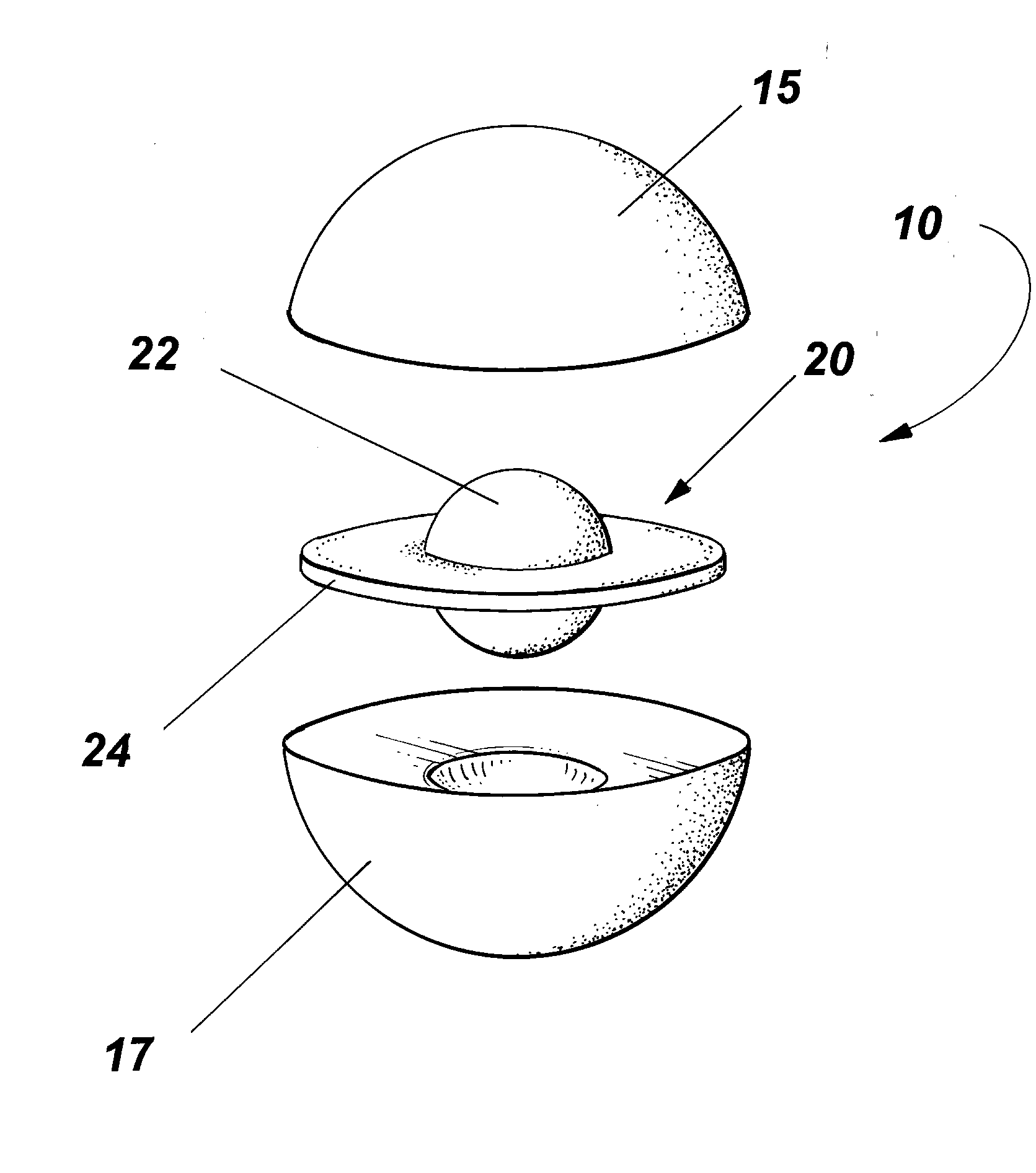
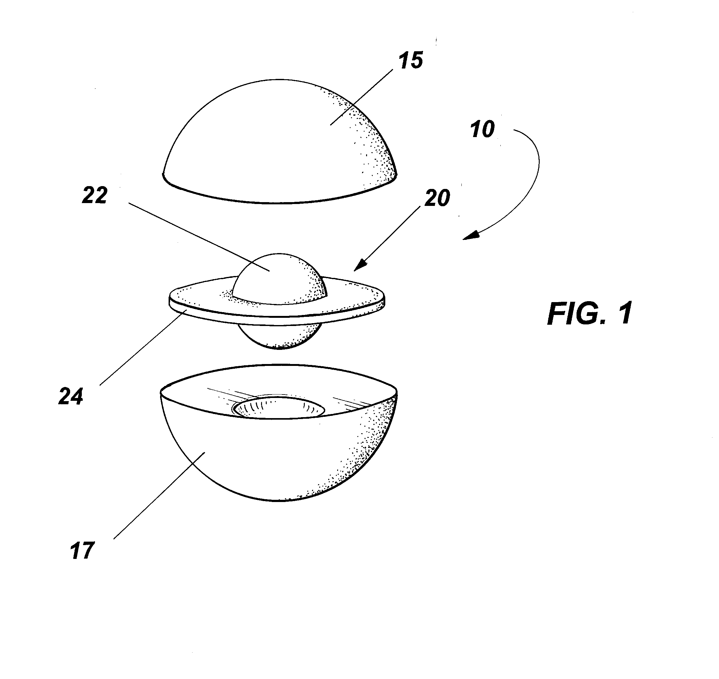
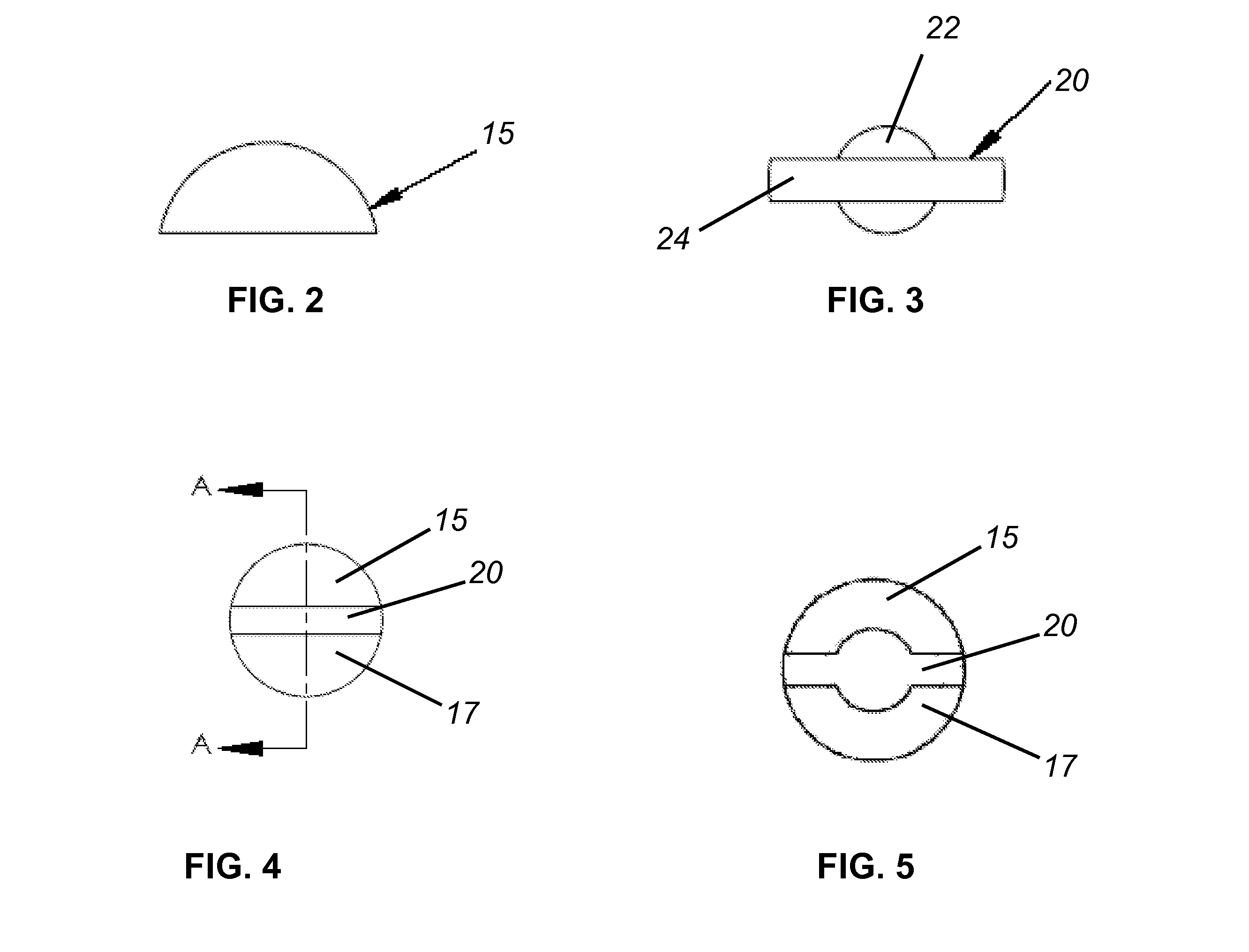
[0023]The present invention provides an apparatus for disc nucleus replacement to promote the support and absorption of axial loads while limiting subsidence and endplate erosion in both vertebral fusion and non-fusion spinal treatments. In non-fusion embodiments, the combination of rigid and compressible components with curved surface portions adapted for placement and contacting the vertebral bodies may further promote motion preservation and dynamic stabilization.

[0024]Although a spinal interbody device of the present invention is described herein in ellipsoid embodiments, including spheres and spheroids, it will be appreciated that various shapes including curved surface portions may be provided in other embodiments.

[0025]Referring to FIGS. 1-5, an interbody device 10 in one embodiment of the invention is a spherical shape. The device 10 includes a top outer shell 15, a bottom outer shell 17 and an inner dampener 20. The outer shells 15 and 17 may comprise sphere portions adapte...


PUM


Abstract

A multi-material spinal interbody device includes an inner dampener of compressible material in combination with a rigid outer material. The rigidity of the outer periphery of curved surfaces of the device, such as in an eluipsoid shape, provide support as a replacement to the nucleus propulsus, with the inner dampener providing for absorption of spinal forces.

Description

CROSS-REFERENCE TO RELATED APPLICATIONS [0001]This application claims priority to patent application Ser. No. 60 / 942,802 filed Jun. 8, 2007, which is relied on and incorporated by reference.BACKGROUND OF THE INVENTION [0002]The present invention relates to fusion and non-fusion spinal interbody devices.[0003]Spinal interbody devices such as the Fernstrom ball developed by Dr. Ulf Fernstrom, the Harmon Spinal Sphere of the Austenal Company (New York, N.Y.) and the more recent Satellite Spinal System of Medtronic Sofamar Danek (Memphis, Tenn.) have attempted stabilization in a disc interspace with an insertable solid sphere. Because of the rigidity and lack of compression of such solid spheres, undesirable subsidence of the device may result leading to possible nerve agitation and further corrective surgery.[0004]Nucleus propulsus replacement has also been attempted with non-rigid hydrogels, such as disclosed in U.S. Pat. No. 7,214,245 to Marcolongo et al. Such hydrogels, however, are...

Claims


Application Information

Patent Timeline
IPC IPC(8): A61F2/44
CPCA61F2/30965A61F2310/00029A61F2/4455A61F2/4611A61F2002/30014A61F2002/30242A61F2002/30245A61F2002/3025A61F2002/30448A61F2002/30563A61F2002/30565A61F2002/30616A61F2002/444A61F2220/005A61F2230/0071A61F2250/0018A61F2310/00017A61F2310/00023A61F2/442A61F2002/30593
Inventor MORRISON, III, THOMAS J.
Owner MEDGEM
Why Eureka
Try Eureka