
Power Generating System Including Modular Wind Turbine-Generator Assembly

a technology of power generation system and wind turbine, which is applied in the direction of motors, electrical devices, dynamo-electric machines, etc., can solve the problems of reducing the overall efficiency of the system, increasing cost and complexity, and consuming unnecessary energy, so as to improve the starting torque of the system and improve the effect of aspect ratio

Inactive Publication Date: 2008-12-18
CLEANFIELD ENERGY CORP
View PDF21 Cites 34 Cited by
  • Summary
  • Abstract
  • Description
  • Claims
  • Application Information

AI Technical Summary

Benefits of technology

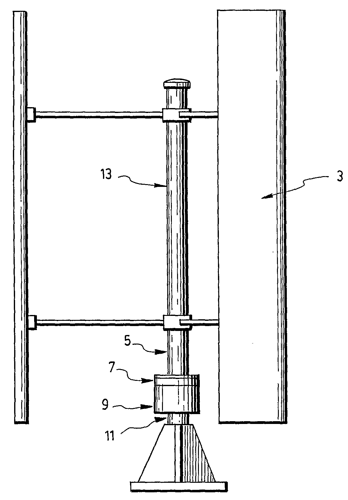
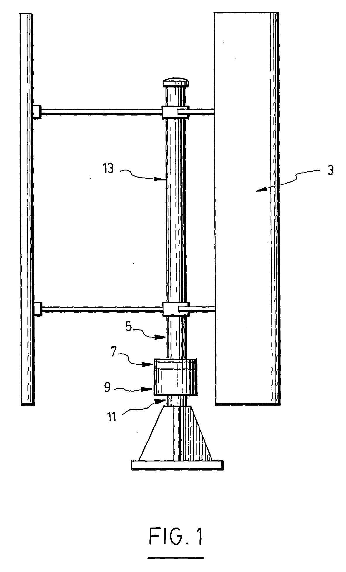
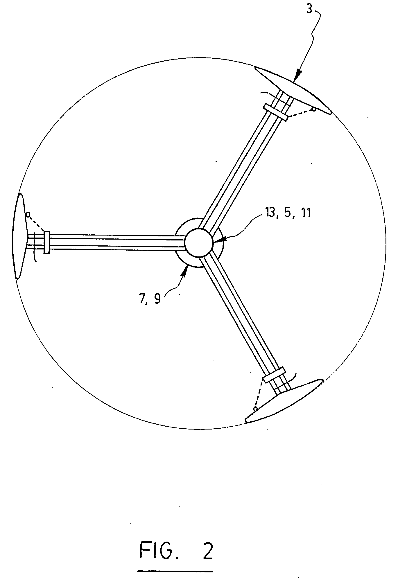
[0022]Preferably also, each mounting spoke has a V-shaped profile for improving a starting torque of the system.
[0023]Preferably also, each aerodynamic blade is provided with corresponding end plates for improving an aspect ratio effect of said each aerodynamic blade.
[0036]Preferably also, the stator comprises windings with tilted slots so as to reduce a cogging torque of the generator assembly.

Problems solved by technology

During normal operation of the rotating device, the electromagnet, being energized, will thus consume unnecessary energy.
Furthermore, the resilient friction between the two braking disks also decreases the overall efficiency of the system, which is undesirable, for obvious reasons.
Every such system has a specific installed power and for increased efficiency, special control methods, power electronics and various generator types are used, adding cost and complexity, and consequently reducing system reliability.
In some cases, the added cost could increase the total cost of the system by more than 50%.
Even with special control methods (field oriented, state estimators, etc.), it would be very difficult to control or provide the necessary generator reactive power needed for variable speed operation.

Method used


Image

  • Power Generating System Including Modular Wind Turbine-Generator Assembly
  • Power Generating System Including Modular Wind Turbine-Generator Assembly
  • Power Generating System Including Modular Wind Turbine-Generator Assembly

Examples


Embodiment Construction

[0059]In the following description, the same numerical references refer to similar elements. The embodiments, dimensions, physical properties and / or geometrical configurations shown in the figures and described herein are preferred variants and are used for exemplification purposes only.

[0060]In the context of the present description, the expression “power generating system” or “assembly” includes all types of turbine-generator assemblies and the like. Although the present invention was primarily designed for use with wind, it could be used with other kinds of driving forces and / or fluids, such as water for example, or with any other suitable items, as apparent to a person skilled in the art. For this reason, the expression “wind”, “wind flow” or any other related derivative form thereof, should not be taken as to limit the scope of the present invention and includes all other kinds of assemblies or items with which the present invention may be used and could be useful.

[0061]Moreove...


PUM


Abstract

A power generating system for generating electricity from the kinetic energy of a wind flow. The power generating system includes a turbine assembly, and a generator assembly, and may be also provided with a main brake assembly, as well as an emergency brake assembly. The system includes a series of modular components which can be built and adjusted in a modular manner so as to alter the configuration of the system, and thus maximize a generation of electricity by the system, depending on the particular conditions of the wind flow. Other improvements reside in the mounting spokes and aerodynamic blades of the system, as well as in its main brake assembly.

Description

FIELD OF THE INVENTION[0001]The present invention relates to a power generating system. More particularly, the present invention, in its preferred intended use, relates to a power generating system including a modular wind turbine-generator assembly that can be used for electricity production, whether grid connected or autonomous, for urban or remote locations, for example. The present invention also relates to a kit for assembling the power generating system, as well as to the method of operating associated thereto.BACKGROUND OF THE INVENTION[0002]Power generating systems, wind turbine-generator assemblies, and the like, are well known in the art, examples of which are described in the following patent applications: US 2003 / 0059306 A1; US 2004 / 0071541 A1; US 2004 / 0184909 A1; DE 297 05410 U1; EP 0,957,265 A2; EP 1,398,500A2; FR 2,541,383; GB 2,033,019 A; GB 2,331,556 A; GB 2,269,859 A; GB 2,404,700 A; WO 03 / 027498 A1; and WO 03 / 040554 A1.[0003]It is also known in the art that the br...

Claims


Application Information

Patent Timeline
IPC IPC(8): F03D3/06F03D11/00
CPCF03D3/005F03D7/0252F03D11/0025F05B2240/214F05B2240/301F05B2240/40H02K7/106H02K7/183H02K49/00Y02E10/74F03D80/40
Inventor STERN, MIHAILTRICA, ALEXANDERVERRELLI, TONYNICOLAE, BUDISANGYULAI, FRANCISC
Owner CLEANFIELD ENERGY CORP
Features
  • Generate Ideas
  • Intellectual Property
  • Life Sciences
  • Materials
  • Tech Scout
  • Unparalleled Data Quality
  • Higher Quality Content
  • 60% Fewer Hallucinations
Learn More