
Method And Device For Creating Marking Lines

a marking line and marking technology, applied in the direction of spray nozzles, coatings, applications, etc., can solve the problems of uncontrollable ejection of one part of the material, regular interruption of work, wet cutting and ejecting devices, etc., to improve the reproducibility of the look of the marking line, facilitate the adjustment of the device, and improve the precision of the material application

Inactive Publication Date: 2008-10-02
HOFMANN MASCHFAB & VERTRIEB
View PDF8 Cites 3 Cited by
  • Summary
  • Abstract
  • Description
  • Claims
  • Application Information

AI Technical Summary

Benefits of technology

[0007]It is the objective of the invention to remedy the aforementioned disadvantages and especially to improve the precision of the material application in terms of size and quality of the individual marking line elements, to facilitate the adjustability of the device, to enable the creation of different types of marking lines, to improve the reproducibility of the look of the marking lines, and to ensure the problem-free functioning of the device in varying the speed of movement in a great speed range.
[0009]The movement of the first and the second discharge element relative to each other achieves, in particular, a steady increase and reduction of the opening cross section, that means a change with fluid passages, thus achieving the desired surface form of the marking line which is composed of droplet-like points or convex bulges. In contrast, an undesirable sudden opening and closing of the opening cross section is here avoided.
[0015]The oscillating movement of the slides can be generated by suitable mechanical drives, e.g. in a driving manner via a crank drive or pneumatically or hydraulically via piston cylinder units, preferably also with a variable oscillation frequency. To avoid undesirable changes in the look of the markings upon changes of the speed of movement relative to the surface to be marked, it is preferably provided, however, that the device comprises a slide drive to ensure a sliding of the slide / slides with a frequency proportional to a speed of movement of the device relative to the surface. The proportionality of the slide drive to the speed of movement of the device can be simply achieved e.g. such that the slider drive being taken over by a travel drive of the device by means of several wheels carrying the device and rolling on the surface to be marked or coupled with at least one of the wheels.
[0016]According to an alternative embodiment of the device, it is provided that the device comprises a housing with a housing bottom forming the first, fixed discharge element and comprising a slot-shaped discharge opening arranged transversely, seen in the direction of movement, and that the opening cross section of the opening is modifiable by means of a hollow cylinder forming the second discharge element and rotatably movable by means of an axis extending transversely to the direction of movement, said hollow cylinder having discharge openings arranged in its jacket surface. The rotation of the hollow cylinder during the movement of the device provides for a steady-periodic opening and closing of the openings by means of the steadily changing covering of the discharge openings in the rotating cylinder jacket on the one hand and in the housing bottom on the other hand.
[0019]A technically relatively simple and at the same time functional design is achieved by the hollow cylinder preferably resting, with the outer circumference of its cylinder jacket, in a sliding manner against two discharge opening edges limiting, on the front and on the rear, the slot-shaped discharge opening in the housing bottom, seen in the direction of movement. These discharge opening edges form one part of the housing bottom and provide, in cooperation with the outer circumference of the hollow cylinder, for the necessary seal between the device parts which are moved relative to each other, to avoid an uncontrolled escape of marking material in other ways than through the openings provided.

Problems solved by technology

A disadvantage of these methods presents the wetting of the cutting and ejecting device rotating outside of the housing holding the material and having the outlet slot.
One part of this material ejected in an uncontrolled manner actually does get onto the road surface, but not at the desired places.
This will result in regular interruptions of the work to free spray protection devices from the material collected there.
For material to be processed hot and solidifying when cooling, there will be additional problems due to material solidifying on the ejecting and spray protection devices when these devices are not heated which is expensive and problematic.
Another problem presents the creation of exact ends of the marking lines.
Although the material discharge from the housing can be abruptly started and ended by abruptly opening and closing the discharge slot; yet, with the known devices, material collected on the cutting and ejecting device will still continue to be ejected, over a longer distance, in an uncontrolled manner and only gradually abating.
Additionally, over a longer distance, material collected on the spray protection devices will drip which also results in undesirable “contaminations” in the breaks of the marking lines.
This method and the pertinent device are not suitable for creating marking lines comprising a plurality of especially droplet-shaped elements.

Method used


Image

  • Method And Device For Creating Marking Lines
  • Method And Device For Creating Marking Lines
  • Method And Device For Creating Marking Lines

Examples


Embodiment Construction

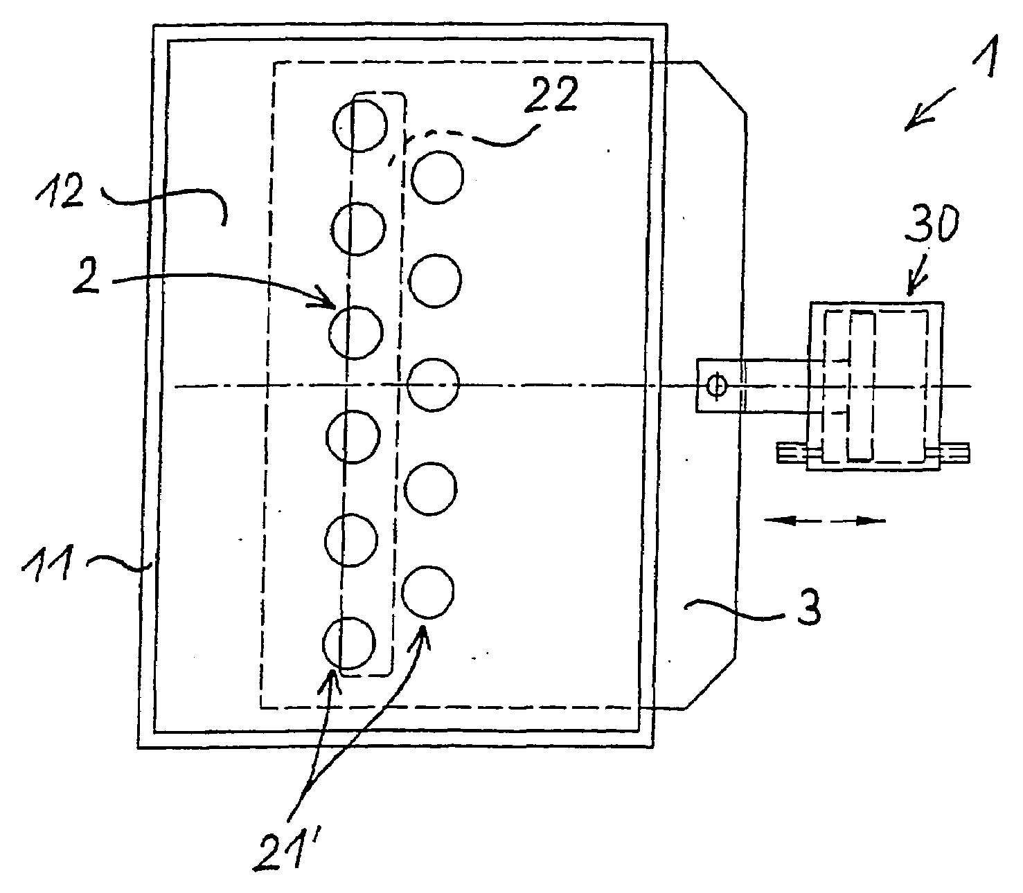
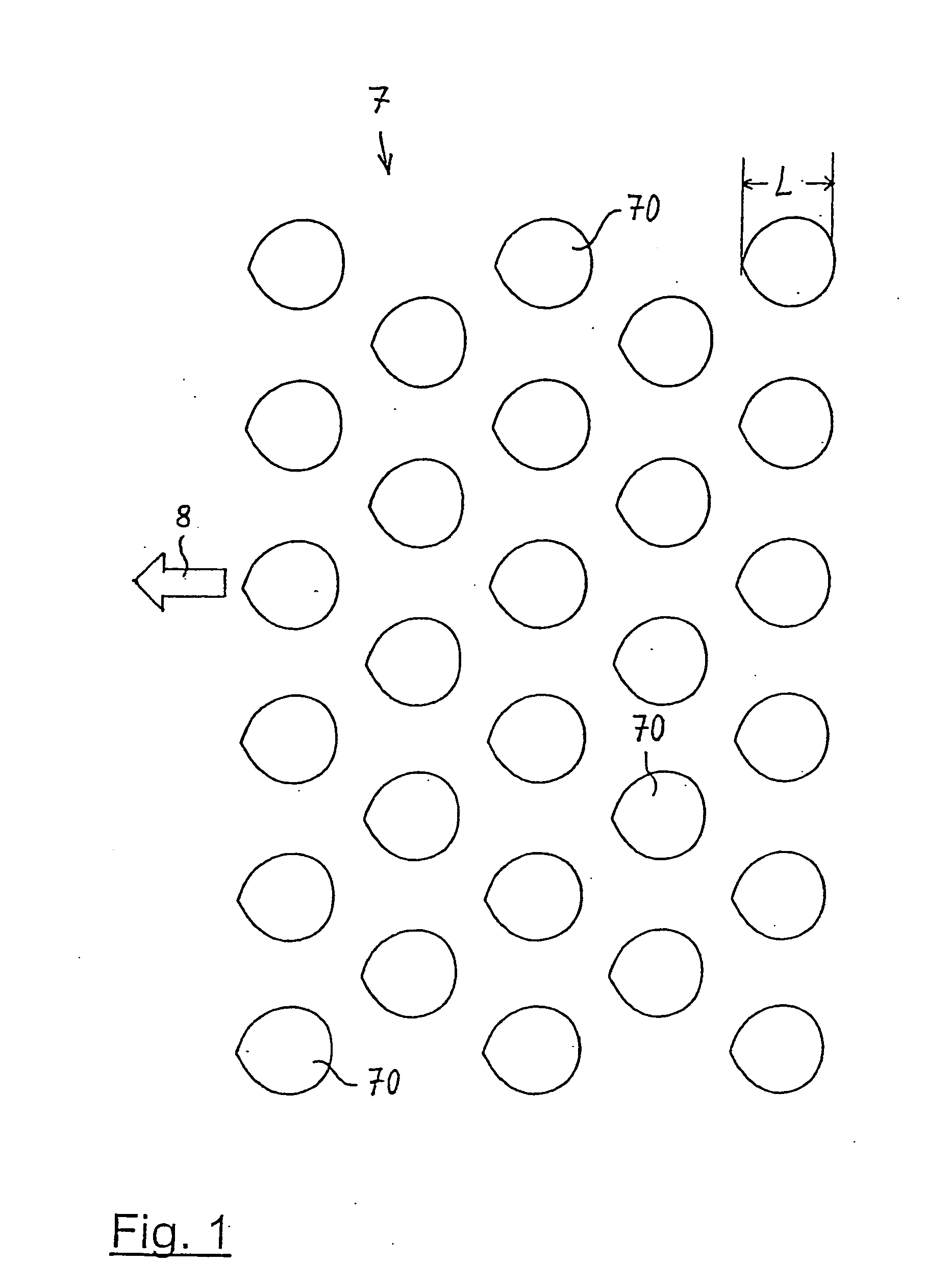
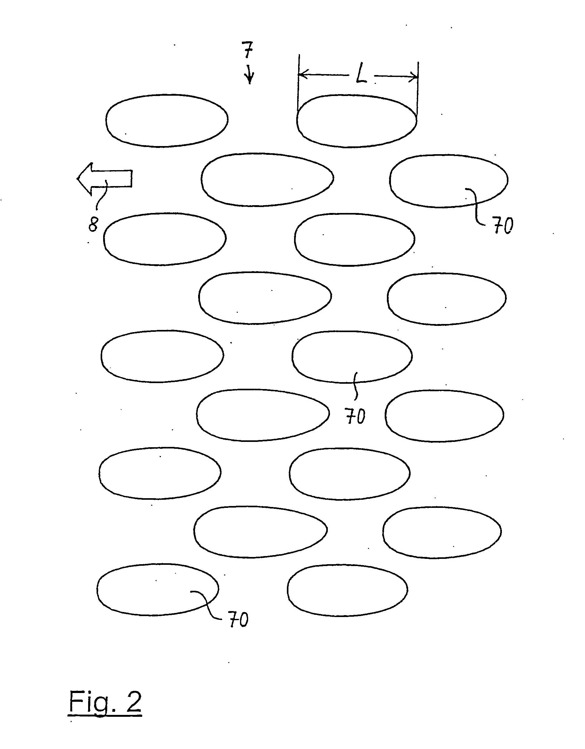
[0043]The examples described hereinafter of the device 1 according to the invention are used for creating marking lines 7 which comprise a plurality of elements 70 and are made of a highly viscous marking material on a surface 6 that is to be marked, especially a road surface. Two examples for such marking lines 7 are presented in FIGS. 1 and 2 in a top view as line sections.

[0044]In the example according to FIG. 1, the individual marking elements 70 have an approximately round, droplet-like form. In the example according to FIG. 2, the individual marking elements 70 have an approximately oval or elliptical form. The longitudinal direction of the marking line 7 extends in direction of the arrow 8 in each case.

[0045]As will yet be explained in the following, the device can furthermore create marking lines which comprise a plurality of bulges extending transversely to the longitudinal direction of the marking lines, as well as the usual continuous marking lines.

[0046]In the examples a...


PUM


Abstract

A device carried on a moving vehicle for creating marking lines, which are a plurality of elements and are made of a highly viscous marking material, on a surface that is to be marked. The device includes a housing formed by walls and a discharge slot formed in at least one of the walls of the housing and extending transversely to a direction of movement of the vehicle, the discharge slot being limited in extent by a front discharge slot edge and a rear discharge slot edge, seen in the direction of movement of the vehicle. A pressurized material supply line leads to an interior of the housing. A rotatable hollow cylinder formed of a jacket is located in the interior of the housing and is arranged to rotate with the movement of the vehicle carrying the device. The cylinder is provided with a plurality of passages through the jacket, which, depending on a rotary position of the cylinder, establish a connection between the pressurized material supply line and the discharge slot. The rotary cylinder is positioned in the housing with an outer circumferential surface of its jacket spaced at a distance from the walls of the housing and essentially forms a sealing gap only in an area of the discharge slot edges.

Description

BACKGROUND OF THE INVENTION[0001]This invention relates to a method for creating marking lines comprising a plurality of elements and comprising a highly viscous marking material on a surface that is to be marked, especially a road surface, with pressurized marking material being discharged through an outlet that can be opened and closed while being moved relative to the surface. Moreover, the invention relates to a device for creating marking lines comprising a plurality of elements and comprising of a highly viscous marking material on a surface that is to be marked, especially a road surface; by means of the device, pressurized marking material can be discharged through an outlet that can be opened and closed while being moved relative to the surface.[0002]For the creation of such markings, the methods and devices according to the documents DK 166 378 and PCT / DK 98 / 00446 have so far become known.[0003]In both known methods, the material emerges as a continuous strip from a slot w...

Claims


Application Information

Patent Timeline
IPC IPC(8): B05C5/00E01C23/24
CPCE01C23/243B05B12/04
Inventor SIBBERS, HARTWIGREIDATH, KLAUS-DIETER
Owner HOFMANN MASCHFAB & VERTRIEB
Features
  • Generate Ideas
  • Intellectual Property
  • Life Sciences
  • Materials
  • Tech Scout
  • Unparalleled Data Quality
  • Higher Quality Content
  • 60% Fewer Hallucinations
Learn More