Road Grader/Spreader System and Method

a grader and spreader technology, applied in the direction of roads, drags, roads, etc., can solve the problems of wasteful and overly expensive rework, wasteful unintended deposition of a greater amount of material, and poor material quality, and achieve the effect of precise depth and slope of material

Inactive Publication Date: 2010-12-30
MULLETT MYRON L
View PDF11 Cites 6 Cited by
  • Summary
  • Abstract
  • Description
  • Claims
  • Application Information

AI Technical Summary

Benefits of technology

[0009]The present invention is a road grader attachment that attaches to a bulldozer. The attachment has an elongated blade with mutually parallel side members attached to the lateral ends of the blade where each of the side members comprise a pair of spaced apart walls that house a plate movable in an up and down direction within the side member. Each of the movable plates is attached at its lower edge to a ground contacting skid. A hydraulic piston or similar in reciprocating device interconnects each side member with its respective interior plate for moving the plate up and down within the side housing member in order to raise or lower the skid that is attached to the movable plate. Up and down movement of the skids with respect to the side members that are attached to the blade results in selective positioning of each end of the blade so their respective elevations above the grade on which the skid rests will result in a precise depth and slope of the material that is being spread.

Problems solved by technology

Machines similar to the Rhoden grader / spreader are satisfactory for their intended agricultural purposes but have limitations when applying and spreading materials for road and highway construction.
In many cases the depth requirement is a minimum figure and unintended deposition of a greater amount of material is wasteful and overly expensive.
Failure to maintain a minimum depth of gravel can result in expensive rework.
In addition, error can occur in the areas of the road between the blue tops.
As a result, considerable time and effort is used to obtain a consistent depth of gravel for a road.
Where the work is being done to construct or resurface a road or highway the rising and falling movement of the grader results in an uneven surface on the material being spread, together with significant departures from the design specification.
Also this does not ensure that the depth between the blue tops is accurate.
If the level of the gravel between the blue tops is too low, this requires expensive rework.
However, this is wasteful and expensive.

Method used


Image

  • Road Grader/Spreader System and Method
  • Road Grader/Spreader System and Method
  • Road Grader/Spreader System and Method

Examples


Embodiment Construction

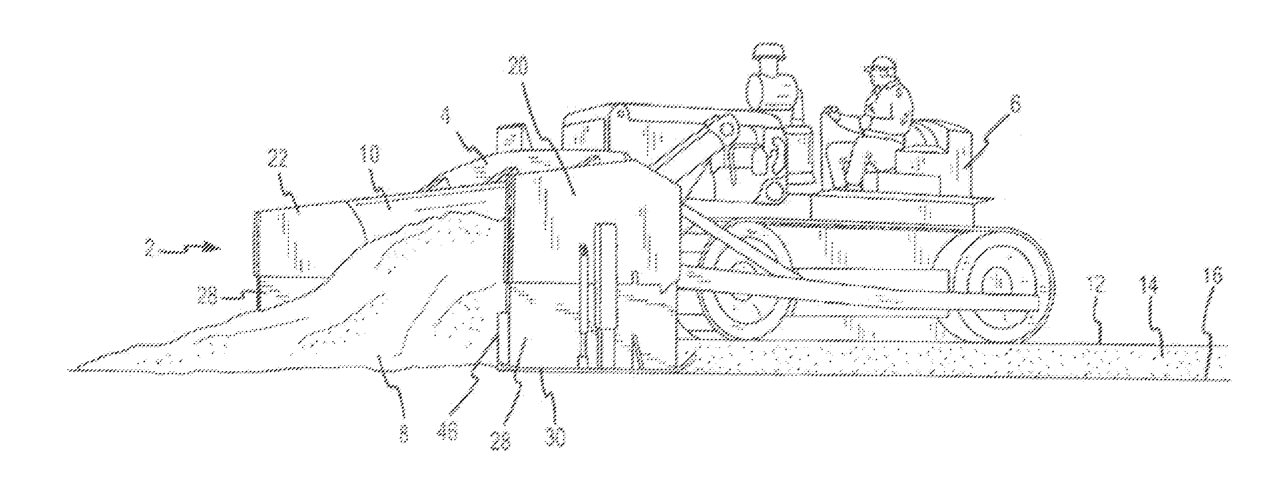
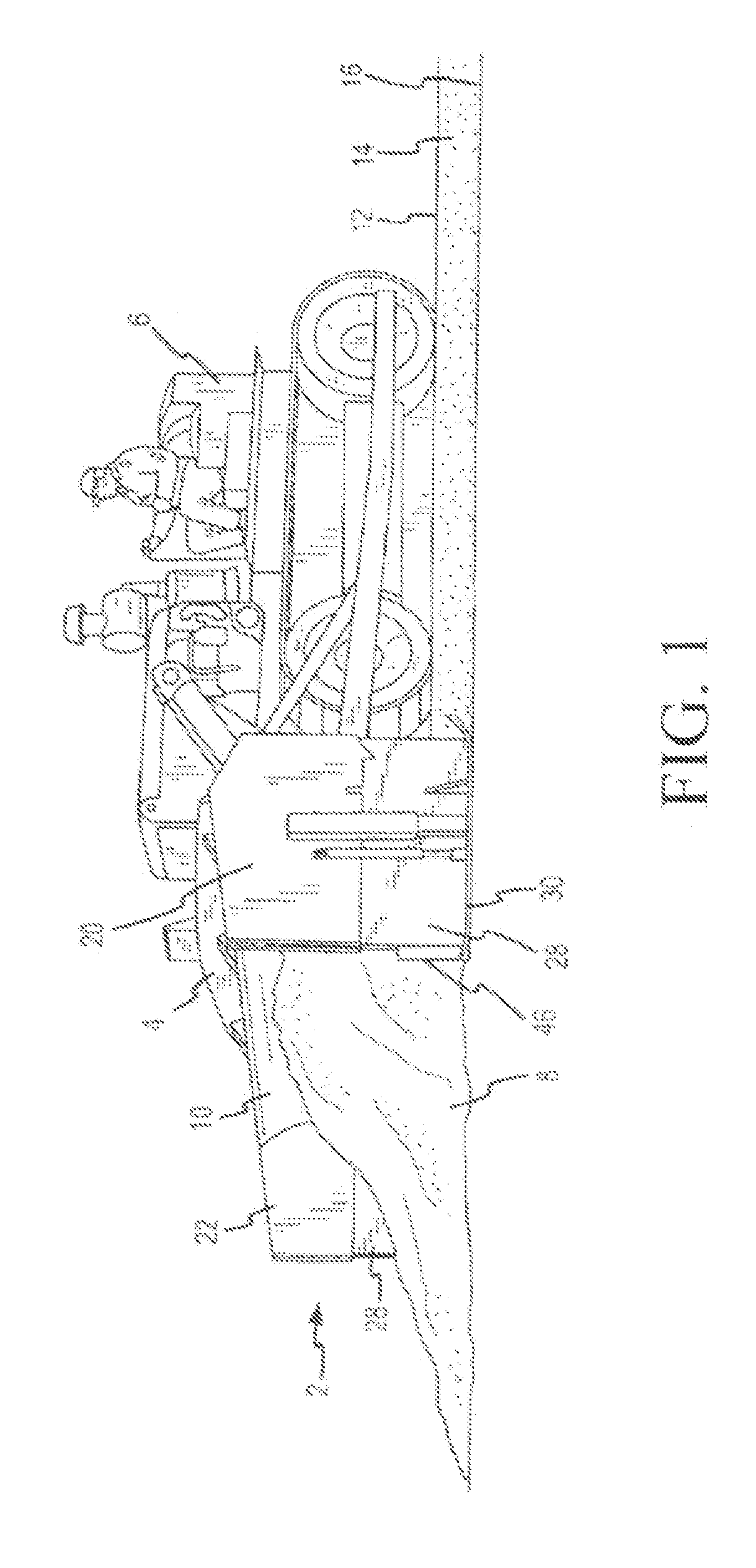
[0017]The grader / spreader 2 of the present invention is shown in FIG. 1 as mounted on and carried by the front blade 4 of a bulldozer 6 is spreading gravel 8 to a specified layer depth. Prior to spreading the gravel is piled in front of the blade 10 of the grader / spreader 2. The bulldozer operates on top of the finished grade 12 of the gravel, or other material that is being spread, thereby assuring a level and constantly accurate depth of the layer 14.

[0018]The depth of the layer 14 above the base grade 16 is controlled by the elevation of the bottom edge of the blade 10 above the base grade. The elevation of each lateral end of the blade 10 may be independently set by hydraulic controls in the cockpit of the bulldozer. This selective adjustment of the height of the blade allows the grade to be sloped from right to left or left to right, or with equal height of each blade end resulting in a level grade.

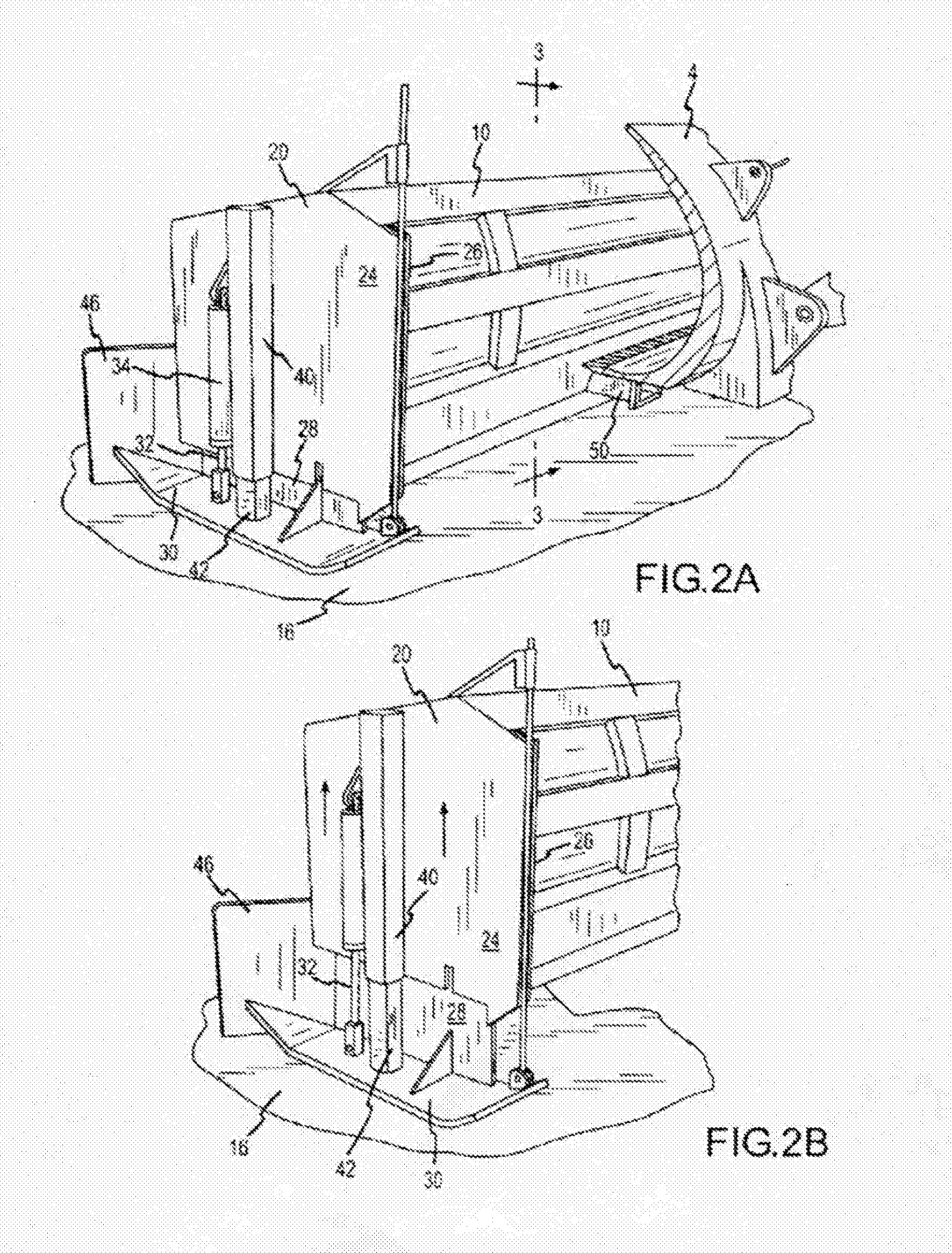
[0019]The novel apparatus for selective adjustment of the height of the blade en...


PUM


Abstract

The present invention is a road grader attachment that attaches to a bulldozer. The attachment has an elongated blade with mutually parallel side members attached to the lateral ends of the blade where each of the side members comprise a pair of spaced apart walls that house a plate movable in an up and down direction within the side member. Each of the movable plates is attached at its lower edge to a ground contacting skid. A hydraulic piston interconnects each side member with its respective interior plate for moving the plate up and down within the side housing member in order to raise or lower the skid that is attached to the movable plate

Description

RELATED APPLICATIONS[0001]The present invention claims priority on patent application Ser. No. 11 / 397,399, filed on Apr. 5, 2006, entitled “Road Grader / Spreader” and is hereby incorporated by reference.STATEMENT REGARDING FEDERALLY SPONSORED RESEARCH[0002]Not ApplicableTHE NAMES OF THE PARTIES TO A JOINT RESEARCH AGREEMENT[0003]Not ApplicableREFERENCE TO A SEQUENCE LISTING, A TABLE, OR A COMPUTER PROGRAM LISTING[0004]Not ApplicableBACKGROUND OF THE INVENTION[0005]The prior art reveals a considerable number of devices designed to spread materials over the ground or over existing layers of material where it is desirable to obtain a finished grade. All of the known apparatus of this kind are towable behind a tractor or similar vehicle. Such a device is disclosed in U.S. Pat. No. 6,308,785 to Rhoden, issued Oct. 30, 2001.[0006]Machines similar to the Rhoden grader / spreader are satisfactory for their intended agricultural purposes but have limitations when applying and spreading material...

Claims


Application Information

Patent Timeline
Patent Type & Authority Applications(United States)
IPC IPC(8): E02F3/85E01C21/00E02F3/815A01B35/20E01C19/48
CPCE02F3/7618E02F3/8157E02F3/8155
Inventor MULLETT, MYRON L.
Owner MULLETT MYRON L
Why Eureka
Try Eureka