Fluid supplying apparatus, fluid ejecting apparatus, and fluid supplying method

Inactive Publication Date: 2008-12-18
SEIKO EPSON CORP
View PDF6 Cites 17 Cited by
  • Summary
  • Abstract
  • Description
  • Claims
  • Application Information

AI Technical Summary

Benefits of technology

[0013]According to the aspects of the invention, the number of the liquid-supply reception ports of the liquid ejecting heads is larger than the number of the liquid-supply channels. Therefore, it is possible to reduce the length of the liquid-supply routes from the liquid

Problems solved by technology

Unfortunately, however, when such a single-main ink-supply scheme is adopted, it is relatively difficult for ink to reach the most downstream tube-joint portion 64A of the most downstream unit recording head 64 that is connected to the most downstream branch ink-supply tube portion 62A of the single ink-supply tube 62.
Disadvantageously, however, the raised pressure could cause the disconnection of a tube(s) or even the blowout of a tube.
In addition to such a risk, it increases the production cost of the ink-

Method used


Image

  • Fluid supplying apparatus, fluid ejecting apparatus, and fluid supplying method
  • Fluid supplying apparatus, fluid ejecting apparatus, and fluid supplying method
  • Fluid supplying apparatus, fluid ejecting apparatus, and fluid supplying method

Examples


example 1

VARIATION EXAMPLE 1

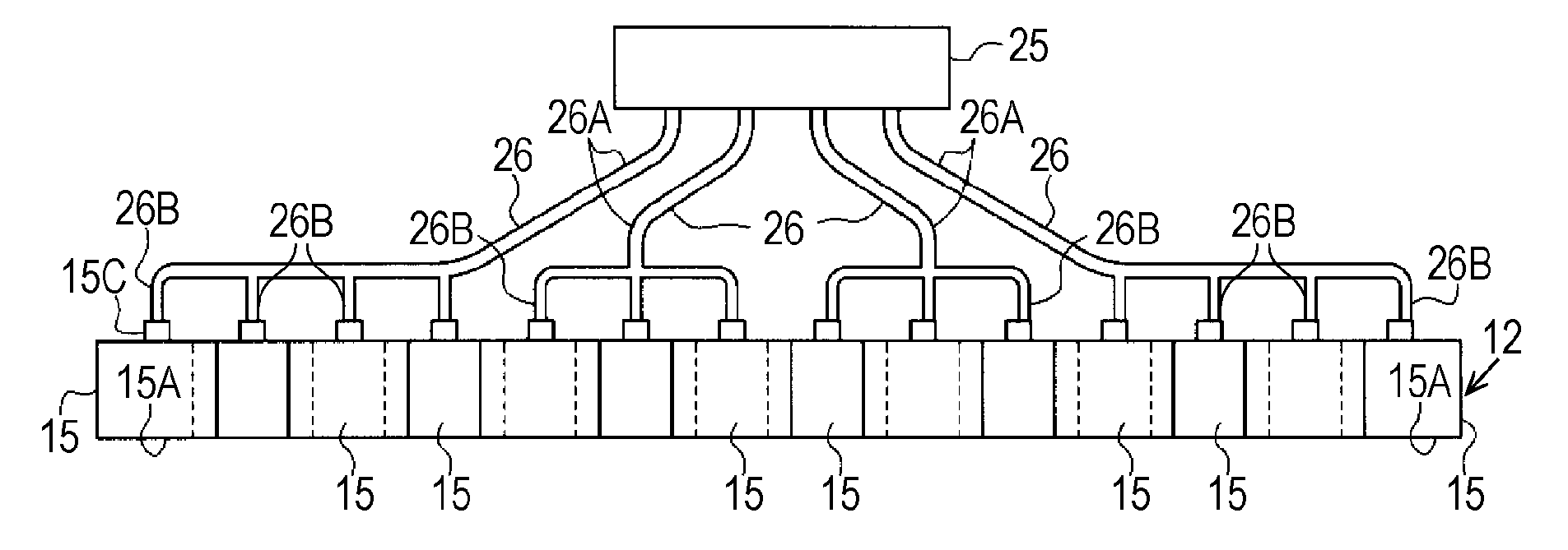
[0048]In the foregoing exemplary embodiment of the invention, the ink-supply tube 26 of the second branch type that has three individual ink-supply tube portions 26B is provided for each end group of three unitary recording heads 15, whereas the ink-supply tube 26 of the first branch type that has four individual ink-supply tube portions 26B is provided for each of two centermost groups of four unitary recording heads 15. However, the scope of the invention is not limited to such an exemplary configuration. For example, as illustrated in FIG. 4, the number of the branch ink-supply tube portions 26B of the ink-supply tube 26 that are connected to the tube-connection projecting portions 15C of the unitary recording heads 15of the two end groups, which is further from the ink cartridge 25, may be larger than the number of the branch ink-supply tube portions 26B of the ink-supply tube 26 that connected to the tube-connection projecting portions 15C of the center-most ...

example 2

VARIATION EXAMPLE 2

[0049]In the foregoing exemplary embodiment of the invention, a single ink cartridge 25 (liquid container) only is provided for ink of one color. However, the scope of the invention is not limited this exemplary configuration. For example, a plurality of liquid containers may be provided for liquid of the same type. In a non-limiting modification example illustrated in FIG. 5, two ink cartridges 45 that contain the same color ink are provided. The pair of ink cartridges 45 comprise non-limiting examples of liquid containers according to the invention. A plurality of ink-supply tubes 26 extends from each of these two ink cartridges 45. Each of the plurality of ink-supply tubes 26 branches into a plurality of individual ink-supply tube portions 26B. Each of the plurality of branch ink-supply tube portions 26B of each of the plurality of ink-supply tubes 26 are connected to the tube-connection projecting portion 15C of corresponding unitary recording heads 15. Herein...

example 3

VARIATION EXAMPLE 3

[0050]As shown in FIG. 6, the plurality of ink-supply tubes 26 that extend from the ink cartridges 45 may have the equal liquid-supply route lengths. In this example, the length of a liquid-supply route is embodied as the length of the ink-supply tube 26 extending from the ink cartridge 45 to the tube-connection projecting portion 15C of the unitary recording head 15. The illustrated tube-connection projecting portion 15C is a non-limiting example of a liquid-supply reception port according to the invention. The illustrated pair of ink cartridges 45 comprise non-limiting examples of liquid containers according to the invention. The illustrated line head 51 comprises a non-limiting example of a liquid ejecting head according to the invention. In the non-limiting modification example illustrated in FIG. 6, the lengths of liquid-supply routes from the ink cartridges 45 to the tube-connection projecting portions 15C of the unitary recording heads 15 are equal. With su...


PUM


Abstract

The invention provides a liquid supplying apparatus that is attached to a liquid ejecting apparatus for supplying liquid to a plurality of liquid ejecting heads of the liquid ejecting apparatus. The liquid supplying apparatus includes: at least one liquid container and a plurality of liquid-supply channels that supply liquid from the least one liquid container to the plurality of liquid ejecting heads by utilizing a difference in the water head difference therebetween. The liquid-supply channels are connected to the at least one liquid container and corresponding liquid-supply reception ports of the plurality of liquid ejecting heads, wherein the number of the liquid-supply reception ports of the liquid ejecting heads is larger than the number of the liquid-supply channels.

Description

BACKGROUND OF THE INVENTION[0001]The entire disclosure of Japanese Patent Application No. 2007-157657, filed Jun. 14, 2007 and Japanese Patent Application No. 2008-104820, filed Apr. 14, 2008 are expressly incorporated herein by reference.[0002]1. Technical Field[0003]The present invention relates to a fluid or liquid supplying apparatus for a liquid ejecting apparatus and a method for supplying liquid to the liquid ejecting heads of the liquid ejecting apparatus.[0004]2. Related Art[0005]In the technical field to which the present invention pertains, an ink-supply apparatus having a single main ink-supply tube or flow channel with a plurality of individual “branches” or individual ink-supply flow channels is known. An example of such an ink-supply apparatus is disclosed in Japanese Patent No. JP-A-2005-22124 (see FIGS. 2 and 3), wherein a single main ink-supply flow channel extends from a main tank. Each of the individual ink-supply flow channels branch off from the single main ink...

Claims


Application Information

Patent Timeline
IPC IPC(8): B41J2/175
CPCB41J2/17509
Inventor TAKAHASHI, NOBUHITO
Owner SEIKO EPSON CORP
Why Eureka
Try Eureka