
Image processing system and image forming apparatus incorporating same

a technology of image processing system and image forming apparatus, which is applied in the direction of image enhancement, visual presentation using printers, instruments, etc., can solve the problems of reducing a time or a space interval, affecting the image quality, so as to increase the size of the image data and the effect of enlarge the image data

Inactive Publication Date: 2008-12-18
RICOH KK
View PDF3 Cites 24 Cited by
  • Summary
  • Abstract
  • Description
  • Claims
  • Application Information

AI Technical Summary

Benefits of technology

[0023]In one exemplary embodiment, the novel image processing system includes a pixel position indicator and a pixel inserting unit. The pixel position indicator is configured to indicate insertion positions in the image data. The pixel inserting unit is configured to enlarge a size of the image data by inserting an additional pixel at each of the insertion positions and accordingly shifting the original pixels in a given direction. The additional pixel has a value lower than a given threshold. Each insertion position is at an approximate center of an area formed of pixels having values higher than the given threshold.
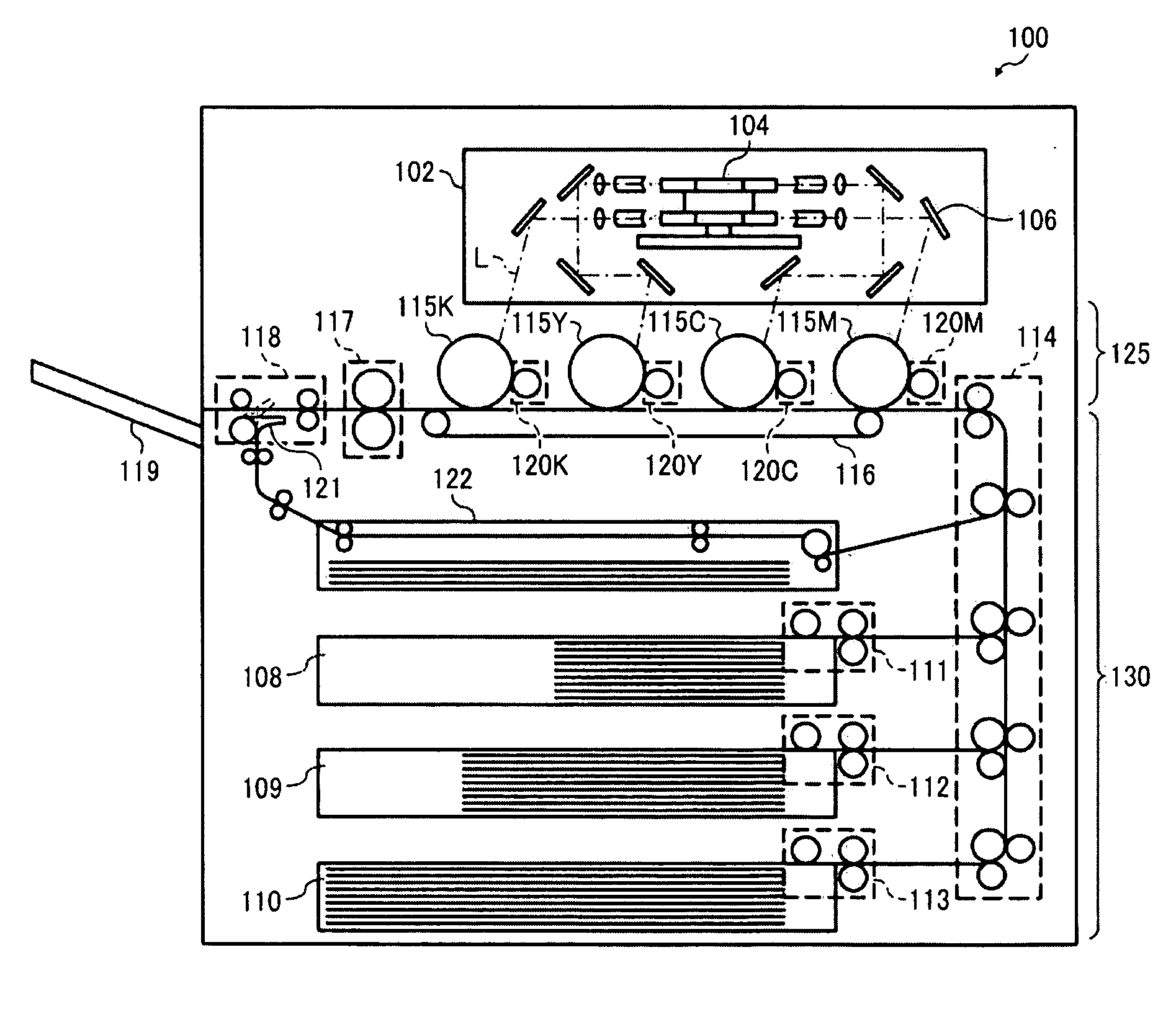
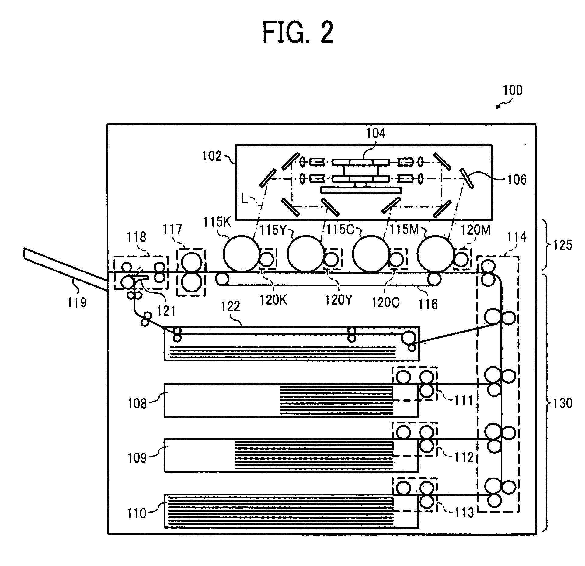
[0024]In one exemplary embodiment, the image forming apparatus includes an image processing system and a electrophotographic system. The novel image processing system is configured to process image data formed of multiple original pixels, and includes a pixel position indicator and a pixel inserting unit. The pixel position indicator is configured to indicate insertion positions in the image data. The pixel inserting unit is configured to enlarge a size of the image data by inserting an additional pixel at each of the insertion positions and accordingly shifting the original pixels in a given direction. The additional pixel has a value lower than a given threshold. Each insertion position is at an approximate center of an area formed of pixels having values higher than the given threshold. The electrophotographic system is configured to form an image by irradiating a photoconductive surface with a laser beam according to the processed image data.

Problems solved by technology

One issue faced by an image data processor employed in an electrophotographic system is the occurrence of errors such as image misalignment or misregistration, which result when multiple images are formed on a single sheet-like recording medium (hereinafter also “recording sheet”).
As a recording sheet tends to shrink slightly when heated, heat application between successive passes causes slight but noticeable misalignment of the images printed on opposite sides of the same sheet.
Such a defect seems to issue from the faster processing speeds and compactness typical of modern electrophotographic printers, which reduces a time or a space interval between successive image formations in the duplex printing mode.
Such errors are commonly encountered by high speed color printers that employ a tandem architecture for reducing processing time.
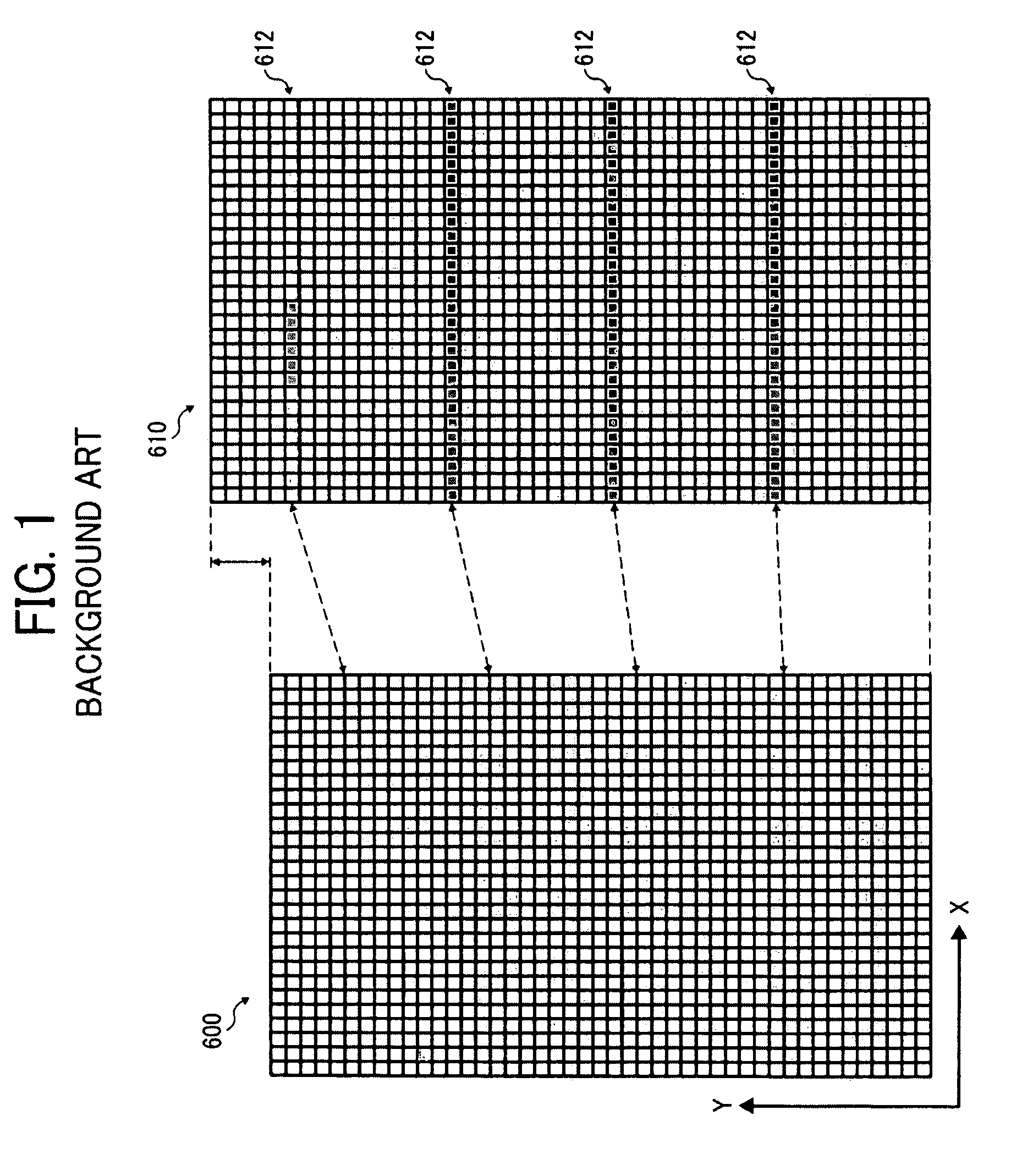
A drawback of such a size adjusting method is that the scaled image tends to suffer from an undesirable pattern of streaks, a print defect commonly known as “banding”.
Generally, artifacts on a printed image such as banding and moiré patterns result from periodic density variations due to various causes, including periodic insertion or deletion of pixels in the image data.
However, when the image has a resolution of 1,200 dots per inch, such pixel insertions translate into density variations in the printed image occurring at approximately 1 cpm, which falls within the range of perception to cause a noticeable banding defect.
Unfortunately, these conventional methods require complex calculations and significant memory capacity in determining where to insert or delete pixels in the image data, increasing manufacturing cost of a printing system implementing the size adjustment capability.

Method used


Image

  • Image processing system and image forming apparatus incorporating same
  • Image processing system and image forming apparatus incorporating same
  • Image processing system and image forming apparatus incorporating same

Examples


experiment 1.1

[0131]The aim of Experiment 1.1 is to investigate how the insertion position and the intensity of inserted pixels affect the efficacy of the scaling operation according to this patent specification, involving images created from image data prepared through screening and size adjustment processes. The conditions of the experiment are given in Example 1 as follows.

example 1

[0132]Binary image data was prepared through screening process to have a resolution of 1,200 dpi with a horizontal line screen of 200 lpi. Size adjustment was performed on the prepared data using various settings so as to obtain different sets of sample image data each of which is enlarged by 2% from the original.

[0133]FIG. 11A shows a portion of the initial data (A0), and FIG. 11B shows corresponding portions of the sample data sets (A1, A2, and A3).

[0134]As shown in the drawing, the initial data A0 has 2 scan lines of foreground pixels or image area in every 6 scan lines corresponding to 1 screen period. Each of the enlarged versions A1 through A3 has an additional 1 scan line on or across the 2-pixel image area after every 8 screen periods.

[0135]The following briefly describes the data samples A1 through A3 obtained in Experiment 1.1.[0136]A1: Each additional scan line was formed of background pixels and inserted next to but not across the 2-pixel image area.[0137]A2: Each additi...

experiment 1.2

[0141]The aim of Experiment 1.2 is to investigate how the effective resolution of the image forming apparatus relative to the theoretical resolution of the image data affects the efficacy of the scaling operation according to this patent specification, using images created from image data prepared through screening and size adjustment processes. The conditions of the experiment are given in Comparative Examples 1 through 3 as follows.


PUM


Abstract

A novel image processing system includes a pixel position indicator and a pixel inserting unit. The pixel position indicator is configured to indicate insertion positions in the image data. The pixel inserting unit is configured to enlarge a size of the image data by inserting an additional pixel at each of the insertion positions and accordingly shifting the original pixels in a given direction. The additional pixel has a value lower than a given threshold. Each insertion position is at an approximate center of an area formed of pixels having values higher than the given threshold. A novel image forming apparatus incorporates such an image processing system and an electrophotographic system. The electrophotographic system is configured to form an image by irradiating a photoconductive surface with a laser beam according to the processed image data.

Description

CROSS-REFERENCE TO RELATED APPLICATIONS[0001]The present patent application claims priority under 35 U.S.C. §119 from Japanese Patent Application No. 2007-154631 filed on Jun. 12, 2007, the entire contents of which are hereby incorporated by reference herein in their entirety.BACKGROUND OF THE INVENTION[0002]1. Field of the Invention[0003]The present invention relates to an image processing system and an image forming apparatus incorporating same, and more particularly, to an image processing system that enlarges image size by inserting additional pixels in an original image, and an image forming apparatus incorporating such an image processing system.[0004]2. Discussion of the Background[0005]As electrophotographic technologies have developed to provide high speed, high definition, and high performance image forming systems, modern image data processors are required to cope with various issues arising from the high quality requirements of such electrophotographic systems.[0006]One ...

Claims


Application Information

Patent Timeline
Patent Type & Authority Applications(United States)
IPC IPC(8): G06K15/02
CPCH04N1/3935H04N1/58
Inventor KISHI, YUMIKOOHIDE, TOSHIOOHYAMA, TATSUOYAMASHITA, HIDETOSHIKAIMA, NOBUYOSHI
Owner RICOH KK
Learn More