Remote-operable micro-electromechanical system based over-current protection apparatus

a micro-electromechanical system and protection apparatus technology, applied in the direction of relays, protective switches using micromechanics, and arrangements responsive to excess voltage, can solve the problems of large circuit breakers, large circuit breakers, and general slow speed of switches of circuit breakers, so as to facilitate the interruption of electrical current passing

Active Publication Date: 2008-12-18
GENERAL ELECTRIC CO
View PDF39 Cites 18 Cited by
  • Summary
  • Abstract
  • Description
  • Claims
  • Application Information

AI Technical Summary

Benefits of technology

[0007]Exemplary embodiments of the present invention include a remote operable over-current protection apparatus. The apparatus may include control circuitry integrally arranged on a current path and a micro electromechanical system (MEMS) switch disposed on the current path, the MEMS switch responsive to the control circuitry to

Problems solved by technology

Traditionally, most conventional circuit breakers include bulky electromechanical switches.
Unfortunately, these conventional circuit breakers are large in size thereby necessitating use of a large force to activate the switching mechanism.
Additionally, the switches of these circuit breakers generally operate at relatively slow speeds.
Further, these circuit breakers are disadvantageously complex to build, and thus expensive to fabricate.
Moreover, energy associated with the arc is generally undesirable to both equipment and personnel.
However, fault currents in power systems are typically greater than the interrupting capacity of the electromechanical contactors.
Unfortunately, contactors such as vacuum contactors do not lend themselves to easy visual inspection as the contactor tips are encapsulated in a sealed, evacuated enclosure.
Further, while the vacuum contactors are well suited for handling the switching of large motors, transformers and capacitors, they are known to cause damaging transient o

Method used


Image

  • Remote-operable micro-electromechanical system based over-current protection apparatus
  • Remote-operable micro-electromechanical system based over-current protection apparatus
  • Remote-operable micro-electromechanical system based over-current protection apparatus

Examples


Embodiment Construction

[0017]In the following detailed description, numerous specific details are set forth in order to provide a thorough understanding of various embodiments of the present invention. However, those skilled in the art will understand that embodiments of the present invention may be practiced without these specific details, that the present invention is not limited to the depicted embodiments, and that the present invention may be practiced in a variety of alternative embodiments. In other instances, well known methods, procedures, and components have not been described in detail.

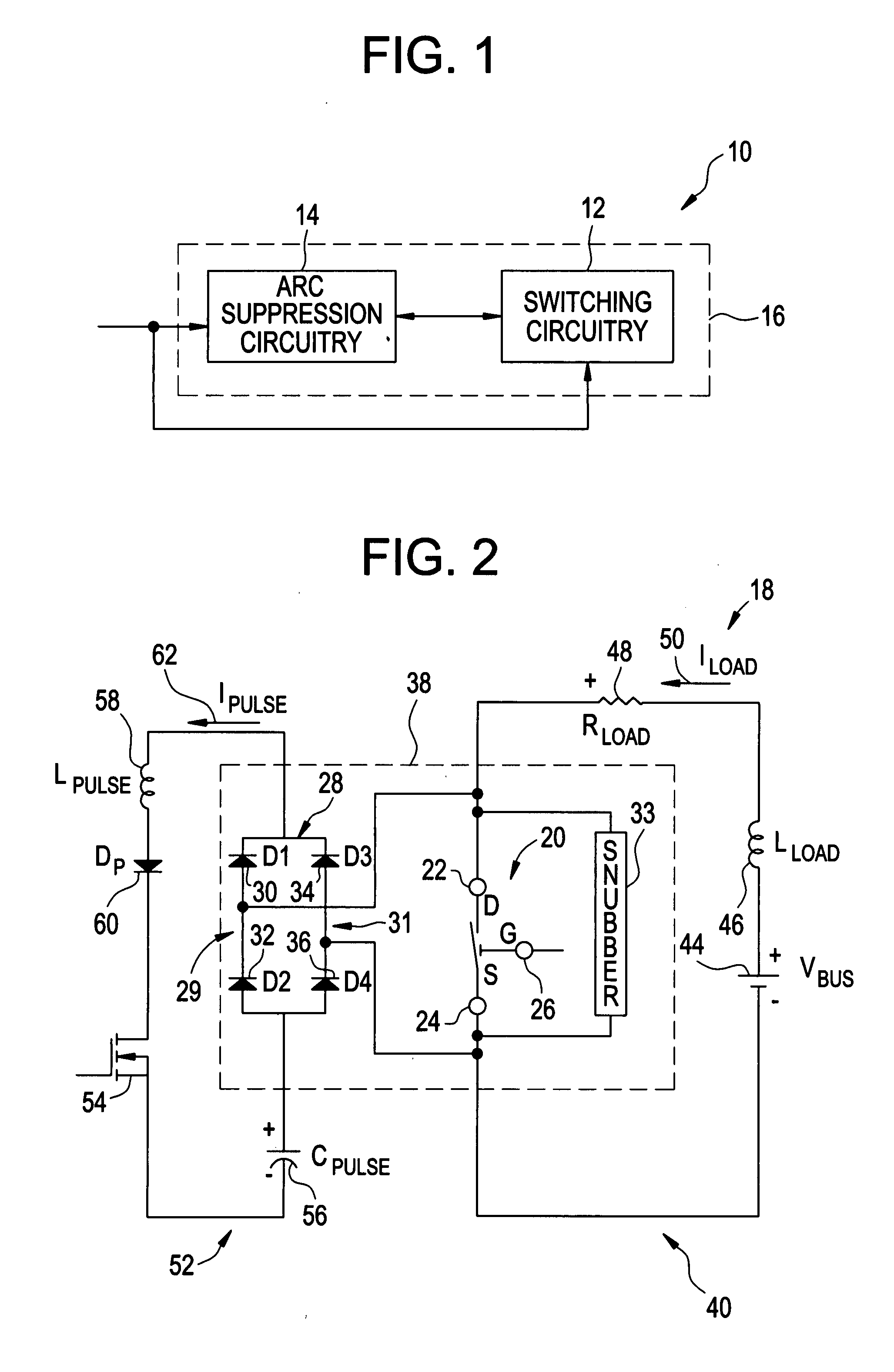
[0018]FIG. 1 illustrates a block diagram of an exemplary arc-less MEMS based switching system 10, in accordance with aspects of the present invention. Presently, MEMSs generally refers to micron-scale structures that, for example, can integrate a multiplicity of functionally distinct elements. Such elements including, but not being limited to, mechanical elements, electromechanical elements, sensors, actuators, a...


PUM


Abstract

The present invention provides a remote operable over-current protection apparatus. The apparatus includes control circuitry integrally arranged on a current path and a micro electromechanical system (MEMS) switch disposed on the current path, the MEMS switch responsive to the control circuitry to facilitate the interruption of an electrical current passing through the current path. The apparatus further includes a communication connection in signal connection with the control circuitry such that the control circuitry is responsive to a control signal on the communication connection to control a state of the MEMS switch.

Description

BACKGROUND OF THE INVENTION[0001]Embodiments of the invention relate generally to a switching device for switching off a current in a current path, and more particularly to micro-electromechanical system based switching devices.[0002]A circuit breaker is an electrical device designed to protect electrical equipment from damage caused by faults in the circuit. Traditionally, most conventional circuit breakers include bulky electromechanical switches. Unfortunately, these conventional circuit breakers are large in size thereby necessitating use of a large force to activate the switching mechanism. Therefore, remote operability of conventional circuit breakers includes large additional mechanical systems capable of producing the large force for activation. Additionally, the switches of these circuit breakers generally operate at relatively slow speeds. Further, these circuit breakers are disadvantageously complex to build, and thus expensive to fabricate. In addition, when contacts of ...

Claims


Application Information

Patent Timeline
IPC IPC(8): H02H3/08H02H3/06H02H3/22
CPCH01H9/30H01H9/541H01H59/0009H01H2071/008H02H3/08H02H7/261
Inventor KUMFER, BRENT CHARLESPREMERLANI, WILLIAM JAMESCAGGIANO, ROBERT JOSEPHSUBRAMANIAN, KANAKASABAPATHIKEIMEL, CHRISTOPHER FREDPITZEN, CHARLES STEPHANLESSLIE, DAVID JAMESTHAKRE, PARAG
Owner GENERAL ELECTRIC CO
Why Eureka
Try Eureka