
Drive unit for a motor vehicle

a technology for motor vehicles and drive units, applied in the direction of gearing control, gearing teeth, instruments, etc., can solve problems such as power failure, and achieve the effect of facilitating disengagement of gears and facilitating the interruption of torque transmission

Inactive Publication Date: 2011-09-27
SCHAEFFLER TECH AG & CO KG
View PDF13 Cites 6 Cited by
  • Summary
  • Abstract
  • Description
  • Claims
  • Application Information

AI Technical Summary

Benefits of technology

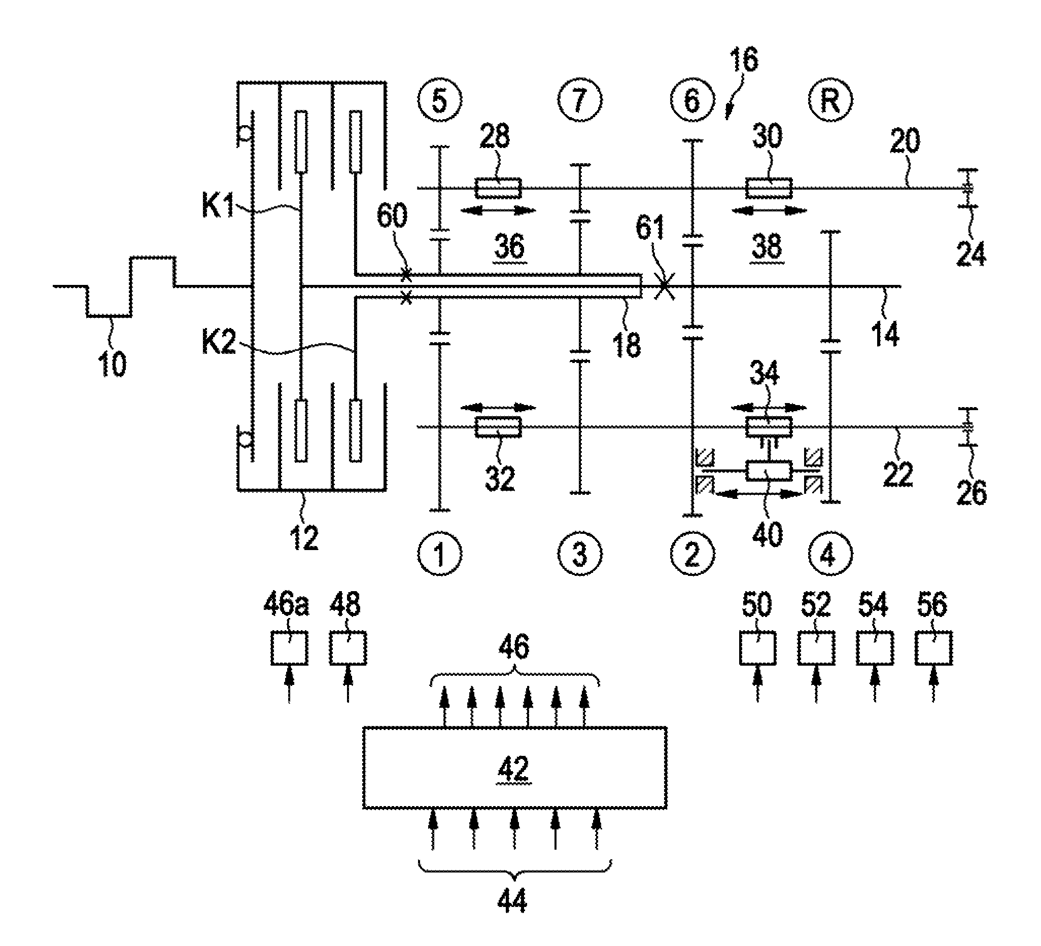
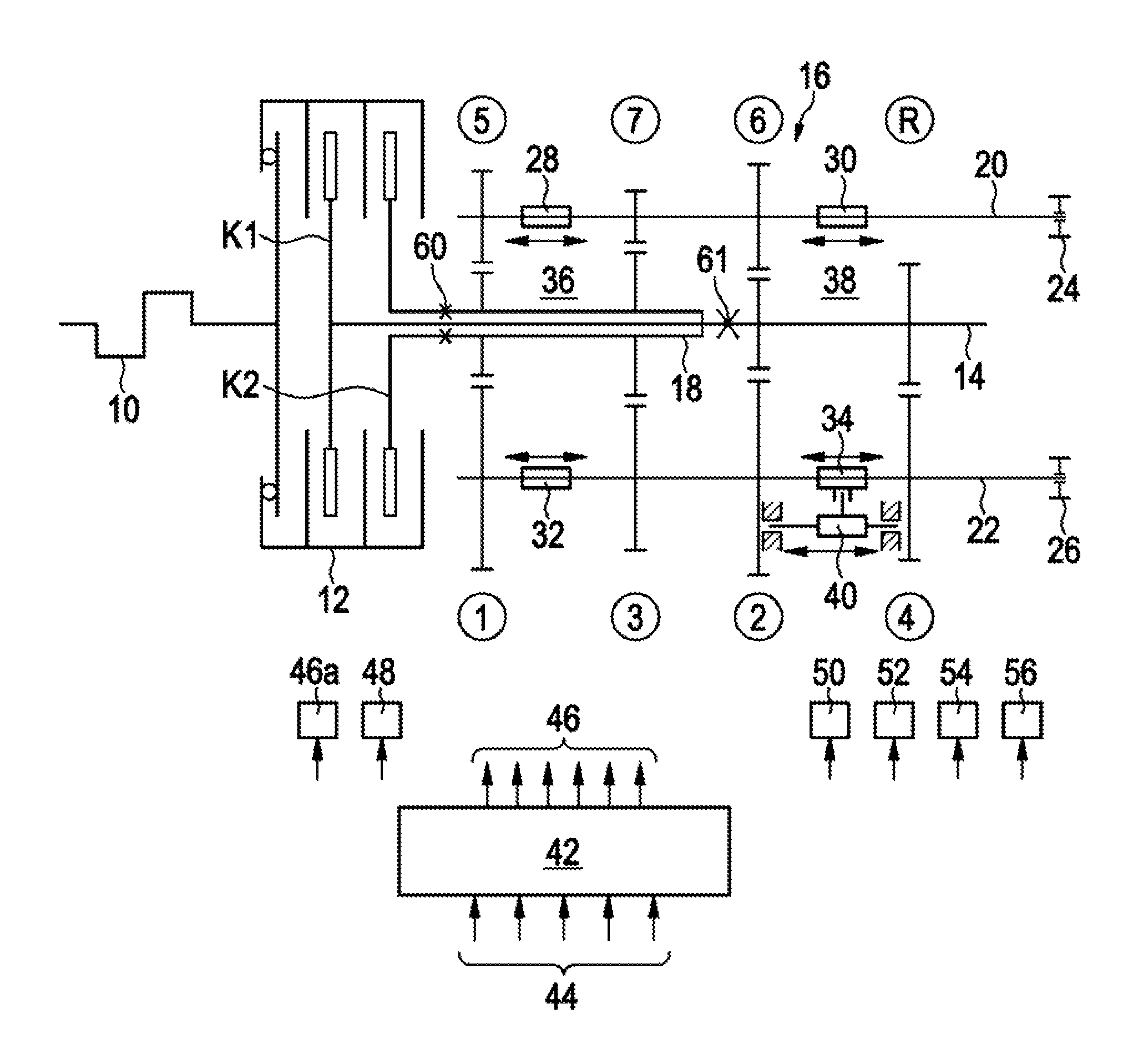
The present invention is a drive unit for a motor vehicle that includes an engine, a transmission or gearbox, and a clutch aggregate for transmitting torque. The clutch aggregate includes at least two friction clutches that are assigned to the input shaft of the transmission or gearbox. One of the friction clutches features an energy accumulator that generates a lock-up force required for torque transmission through the clutch aggregate. The control unit automatically activates the at least two friction clutches and the transmission or gearbox. In the event of a malfunction of the activation of one of the friction clutches, the stored energy in the accumulator creates an interruption of torque transmission within a section of the drive unit connected downstream of the clutch aggregate. This interruption can take place within the transmission or gearbox, and means for interruption of torque transmission can include the opening of an auxiliary clutch or the disengagement of a gear. The invention aims to provide a reliable and effective solution for ensuring safe and smooth operation of the drive unit in the event of a malfunction.

Problems solved by technology

The reasons for such malfunctions within the control device and the actuators controlled by this control device are, for example, power failures that interrupt the hydraulic and / or pneumatic and / or electric power supply to the respective actuators.
A cause of power failure, for instance, can be a fallen connector or failure of a circuit breaker.

Method used


Image

  • Drive unit for a motor vehicle
  • Drive unit for a motor vehicle

Examples


Embodiment Construction

At the outset, it should be appreciated that like drawing numbers on different drawing views identify identical, or functionally similar, structural elements of the invention. While the present invention is described with respect to what is presently considered to be the preferred aspects, it is to be understood that the invention as claimed is not limited to the disclosed aspects.

Furthermore, it is understood that this invention is not limited to the particular methodology, materials and modifications described and as such may, of course, vary. It is also understood that the terminology used herein is for the purpose of describing particular aspects only, and is not intended to limit the scope of the present invention, which is limited only by the appended claims.

Unless defined otherwise, all technical and scientific terms used herein have the same meaning as commonly understood to one of ordinary skill in the art to which this invention belongs. Although any methods, devices or ma...


PUM


Abstract

A drive unit for a motor vehicle, comprising an engine, a transmission or gearbox, a clutch aggregate for transmitting torque, the clutch aggregate including at least two friction clutches that are assigned to an input shaft of the transmission or gearbox, wherein at least one of the at least two friction clutches features an energy accumulator operatively arranged to generate a lock-up force required for torque transmission through the clutch aggregate, and a control unit operatively arranged to control an automatic activation of the at least two friction clutches and the transmission or gearbox, wherein in the event of a malfunction of the activation of the friction clutch, the stored energy in the accumulator creates an interruption of torque transmission within a section of the drive unit connected downstream of the clutch aggregate.

Description

FIELD OF THE INVENTIONThe invention relates to a drive unit for a motor vehicle, comprising at least a drive engine, transmission (gearbox) and a clutch unit that ensures the transmission of torque between the latter and has at least two friction clutches which are each assigned to transmission (gearbox) input shaft, wherein at least one of the friction clutches features at least an energy accumulator that at least essentially generates the lock-up force required for torque transmission, so that this friction clutch automatically assumes a closed state. In such drive units, at least the friction clutches and the gearbox but in many cases, the engine as well as an internal combustion engine is actuated automatically or semi-automatically by means of at least a control unit or device.BACKGROUND OF THE INVENTIONDrive units for motor vehicles of the type mentioned above are, for instance, proposed by DE 10 2005 061 078 A1, DE 103 08 700 A1, and DE 103 08 698 A1. Special designs of the s...

Claims


Application Information

Patent Timeline
Patent Type & Authority Patents(United States)
IPC IPC(8): F16H3/093F16H61/12
CPCF16H61/12F16H61/688F16H2061/1224F16H2061/128Y10T74/19228Y10T74/19233Y10T477/641Y10T477/6403Y10T477/75Y10S477/906
Inventor VENNEMANN, KLAUS-GUENTER
Owner SCHAEFFLER TECH AG & CO KG
Learn More