
Graphical data processing

a graphical data and processing method technology, applied in the field of graphical data processing, can solve the problems of difficult to efficiently distribute such models, difficult to achieve dynamic control, and inability to achieve remote access, etc., to achieve high frame transmission rate, facilitate dynamic control, and improve image quality

Inactive Publication Date: 2009-11-05
BRITISH TELECOMM PLC
View PDF3 Cites 7 Cited by
  • Summary
  • Abstract
  • Description
  • Claims
  • Application Information

AI Technical Summary

Benefits of technology

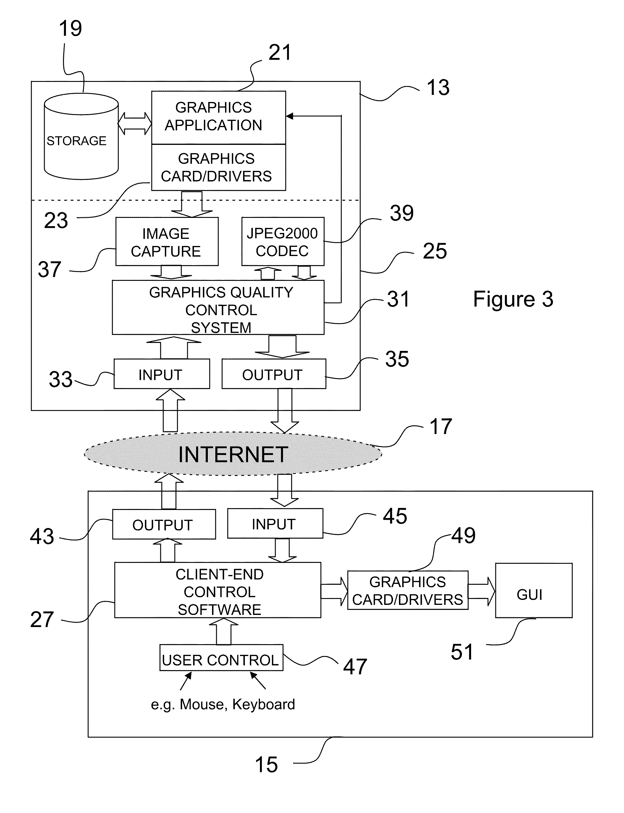
[0006]The method enables image processing to be performed locally, i.e. co-local with the image / model dataset, using image compression to provide each image-to-be-transmitted as a plurality of image layers, each layer having a different degree of compression. Unlike conventional techniques where all image layers are transmitted in a single file / message and decompressed at the client end, here we transmit each image layer separately and so transmission of individual layers can be interrupted at any time, for example in response to interaction at the client, to reduce the amount of overall data that is sent from server to client.
[0014]The method enables image processing to be performed locally, i.e. co-local with the image / model dataset, in accordance with quality settings particular to, and received from, a remote terminal. With restricted bandwidth between the two computers, this allows the user to control, in real-time, the quality of graphical data displayed at their end dependent on if and how the user is manipulating the data. For a given bandwidth, there is a trade-off between image quality and transmitted frame rate and the user has the ability to determine the degree to which one is preferred over the other. For example, in a first manipulation mode where there is, in fact, no manipulation, a higher image quality will usually be preferred over transmission rate since the displayed image will not change over successive frames. On the other hand, in a different manipulation mode where successively-transmitted image frames will change, e.g. due to a rotation command, the transmission rate becomes a factor. If the user requires a smooth transition between frames, a high frame transmission rate will be preferred at the expense of image quality.
[0015]In the preferred embodiment, respective image quality settings for such static and moving scenarios are set and transmitted from the client end. At said client end, the settings can be made using two slider bars which enable a user to adjust settings interactively and, taking into account some small amount of network latency, to view the resulting effects on the data received from the processing end. Dynamic control is therefore facilitated.
[0016]The image quality is preferably adjusted by its degree or type of compression. In the preferred embodiment, we employ a Discrete Wavelet Transform (DWT) algorithm based on JPEG2000 which is shown to improve the quality of images at higher levels of compression. Details of the JPEG2000 standard are available at http: / / www.jpeg.org / jpeg2000 / . The algorithm provides multiple quality layers for an image. Accordingly, for each image to be transmitted to the remote computer, the image is preferably first compressed into multiple layers and, thereafter, layers are progressively transmitted depending on the current manipulation mode. Initially, the lowest quality layer is transmitted. If no new image (or a duplicate image) is required, then the image data comprising the next quality layer is sent. At the remote computer, the corresponding codec adds this to the previous layer and a higher quality image is displayed. This continues until either the image changes, e.g. due to manipulation, or all quality layers have been sent. This facilitates the interruption of the progressively improving image quality to recommence transmission of standard quality images in response to user manipulation.

Problems solved by technology

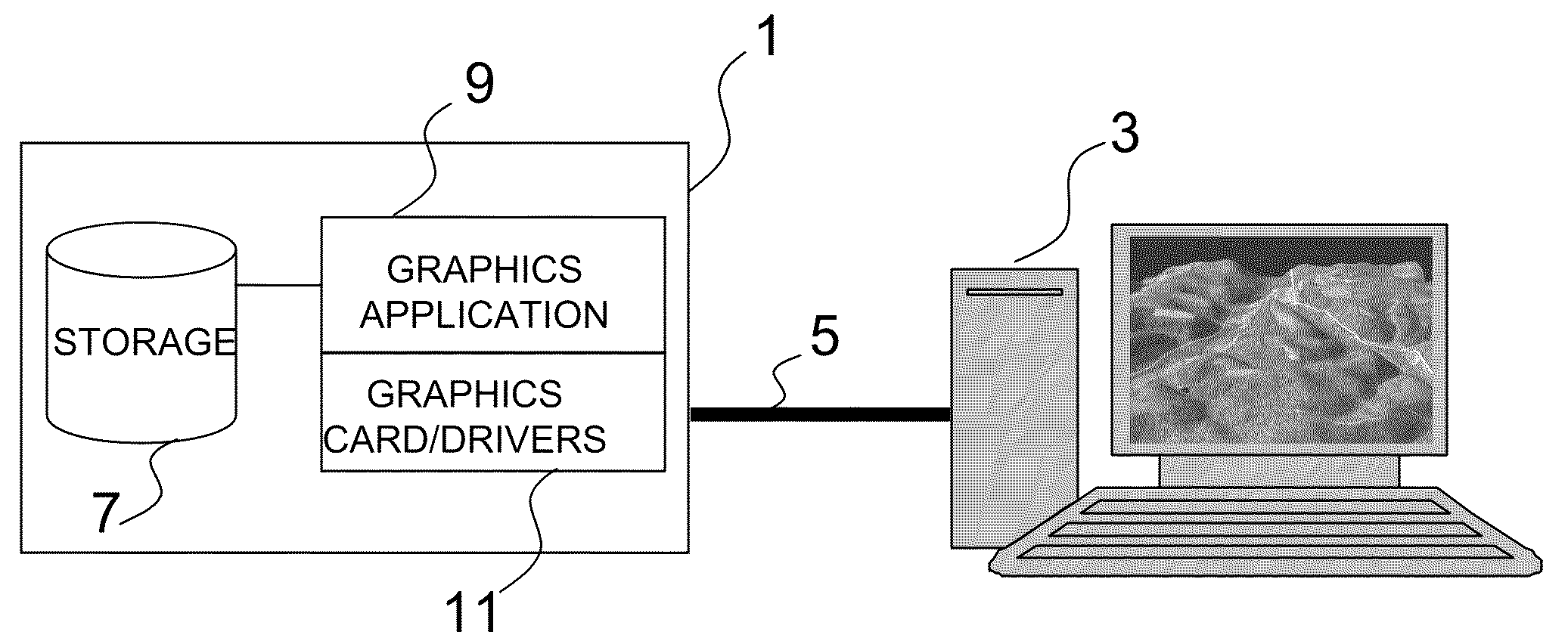
Such applications generate huge datasets which make it difficult to distribute such models in an efficient way, particularly over data networks.
These size and access issues therefore require the dataset and processing functionality to be co-located and make remote access impractical.
Another challenge is the latency of the data connection.
Higher latency networks, such as the Internet or satellite-based networks, generally exhibit poor responsiveness to remote user input, especially with protocols that require multiple round trips to convey commands, keyboard inputs and / or mouse movement.

Method used


Image

  • Graphical data processing
  • Graphical data processing
  • Graphical data processing

Examples


Embodiment Construction

[0027]FIG. 1 was described above in relation to the prior art and is useful for understanding the background of the present method / system which is described with reference to FIGS. 2 to 4 of the drawings.

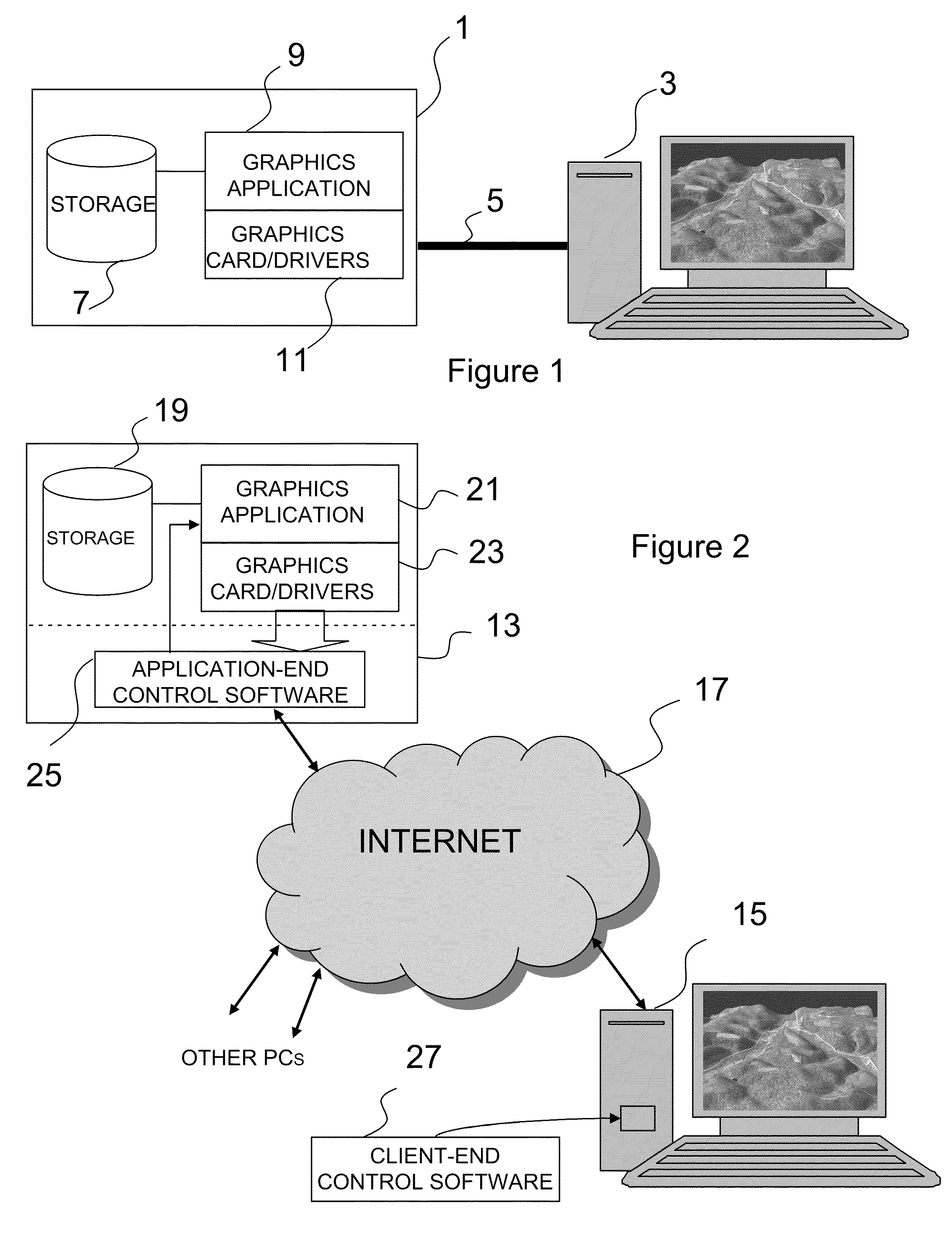
[0028]Referring to FIG. 2, an application server 13 is shown connected to a client terminal 15 via the Internet 17. The Internet 17 is used as the intervening data network in this embodiment since it exemplifies the sort of lower-bandwidth, higher-latency network with which the method / system offers particular advantages. A satellite network has similar bandwidth / latency issues, although the reader will appreciate that it is not intended to restrict the method / system to these network types.

[0029]The application server 13 is similar to that shown in FIG. 1 in that it comprises a storage facility 19 for storing 3D model data, a graphics application 21 and graphics card / drivers 23. In addition, however, we provide application-end control software 25 which, in effect, sits between the gr...


PUM


Abstract

A method and system 13 for processing graphical data for transmission to a remote computer 15 via a data network 17, the graphical data representing an image or graphical model the display of which can be manipulated at the remote computer in real-time in accordance with control commands, for example in response to keyboard or mouse inputs 47. The method / system involves receiving, from the remote computer, image quality settings associated with respective manipulation modes. A current manipulation mode is identified based on control commands received from the remote computer, for example in response to detecting whether or not a user is interacting with the image or model. The graphical data is then processed in accordance with the image quality settings for the identified current manipulation mode to generate an updated image or set of images for transmission to the remote computer. The processing involves using a compression algorithm to generate data representing a plurality of image layers L1 . . . Ln for the current image, L1 having the highest degree of compression and Ln the least. Data representing the image layers is transmitted to the remote computer in sequence from L1 towards Ln, the layers being transmitted as individual files / messages. Said transmission can be interrupted to stop layers in the sequence being transmitted in response to receiving a signal from the remote computer, for example a signal indicative of user interaction.

Description

FIELD OF THE INVENTION [0001]This invention relates to a method and system for processing graphical data, for example data representing a three-dimensional model.BACKGROUND TO THE INVENTION [0002]Computer applications providing visualization in three-dimensions (3D) are known. For example, it is known to provide 3D visualizations of seismic and other geophysical data to enable scientists / engineers to evaluate terrain conditions in remote areas which can be useful for planning purposes, detecting potential operational problems and so on. Such applications generate huge datasets which make it difficult to distribute such models in an efficient way, particularly over data networks. In some countries, there are also legal restrictions in place which prevent the datasets leaving the country and which therefore oblige local processing. These size and access issues therefore require the dataset and processing functionality to be co-located and make remote access impractical. To exemplify t...

Claims


Application Information

Patent Timeline
Patent Type & Authority Applications(United States)
IPC IPC(8): G06K9/36
CPCH04N19/132H04N19/64H04N19/187H04N19/164
Inventor LOCK, GORDON D.BRYCE, ANDREWBARNSLEY, JEREMY
Owner BRITISH TELECOMM PLC
Learn More