Apparatus and method for mounting and removing tyres on and from respective wheel rims

a technology of tyres and tyres, which is applied in the field of apparatus and a method for mounting and removing tyres on and from respective wheel rims, can solve the problems of tyre damage, bead adhesion, and rubble to vulcanize, and achieve the effect of reliable and precise manner

Active Publication Date: 2014-07-15
NEXION SPA
View PDF16 Cites 5 Cited by
  • Summary
  • Abstract
  • Description
  • Claims
  • Application Information

AI Technical Summary

Benefits of technology

[0041]In particular, this invention has for an aim to provide an especially reliable apparatus and method for mounting and removing tyres on and from respective wheel rims that enables to make available useful data to detect and possibly prevent cases of tyre bead damage.
[0042]Another aim of the invention is to provide an apparatus and method for mounting and removing tyres on and from respective wheel rims that makes it possible to mount and remove any tyre without the risk of damaging tyre beads.
[0044]Thus, the apparatus and method according to the invention allow tyres to be mounted and removed on and from respective rims with the possibility of measuring the mechanical strain applied to the tyre bead while the latter is deformed so it can be coupled / uncoupled to / from the rim.
[0051]This makes it possible to generate a feedback signal when the measured strain reaches a predetermined reference value, said signal enabling the operator to promptly interrupt the mounting or removal process before damage is done to the tyre bead or at least to realize the risk of damage and thus give the possibility of scrapping a potentially damaged tyre.
[0056]The possibility of generating alerting signals or of applying the above mentioned types of control (on the mounting / removing tool that interacts with the bead or on the means that turn the wheel) according to these parameters allows particularly precise and effective monitoring of the mechanical stress the tyre bead is subjected to and also reduces the risk of interrupting or slowing down the mounting or removal process unless strictly necessary.

Problems solved by technology

During removal, on the other hand, the pressure disc is used to detach the tyre bead from the rim (in effect, during use, the tyre becomes very hot, causing the rubber to vulcanize, thereby making the bead adhere to the wheel rim).
In effect, when mounting the tyre on the rim, the bead is subjected to mechanical strain that often leads to tyre damage.
All these types of mechanical strain on the bead, if they exceed certain limits (specified by tyre manufacturing associations and automobile constructors) may lead to serious tyre damage.
In this regard, it must be stressed that the risk of damage to the bead is particularly serious if it occurs during mounting because, once the tyre has been mounted, the damage, if any, is not visible before the tyre is used.
Further, the problem is felt particularly strongly on account of the use of run flat tyres, that is, tyres designed to resist the effects of deflation.
Thus, in the event of a failure, a long time might pass before the driver realizes the tyre is damaged.
In fact, tyre manufacturers now tend to make tyres harder and with the shoulder lower down: this worsens the problem of damage to the tyre during mounting and removal.
However, this solution does not allow accurate and reliable measurement of the mechanical strain the tyre bead is subjected to during mounting and removal.
A great deal of the strain applied the bead is subjected to, however, is absorbed by the elasticity of the tool mounting structures.
Moreover, the flexibility of the tools is limited and variable in time.
This solution cannot therefore be used to obtain really useful and effective information on the mechanical strain applied to the bead and potentially able to damage the bead.
However, also this solution does not allow accurate and reliable measurement of the mechanical strains the tyre bead is subjected to during mounting and removal, nor allows the monitoring of the trend of said strains.

Method used


Image

  • Apparatus and method for mounting and removing tyres on and from respective wheel rims
  • Apparatus and method for mounting and removing tyres on and from respective wheel rims
  • Apparatus and method for mounting and removing tyres on and from respective wheel rims

Examples


Embodiment Construction

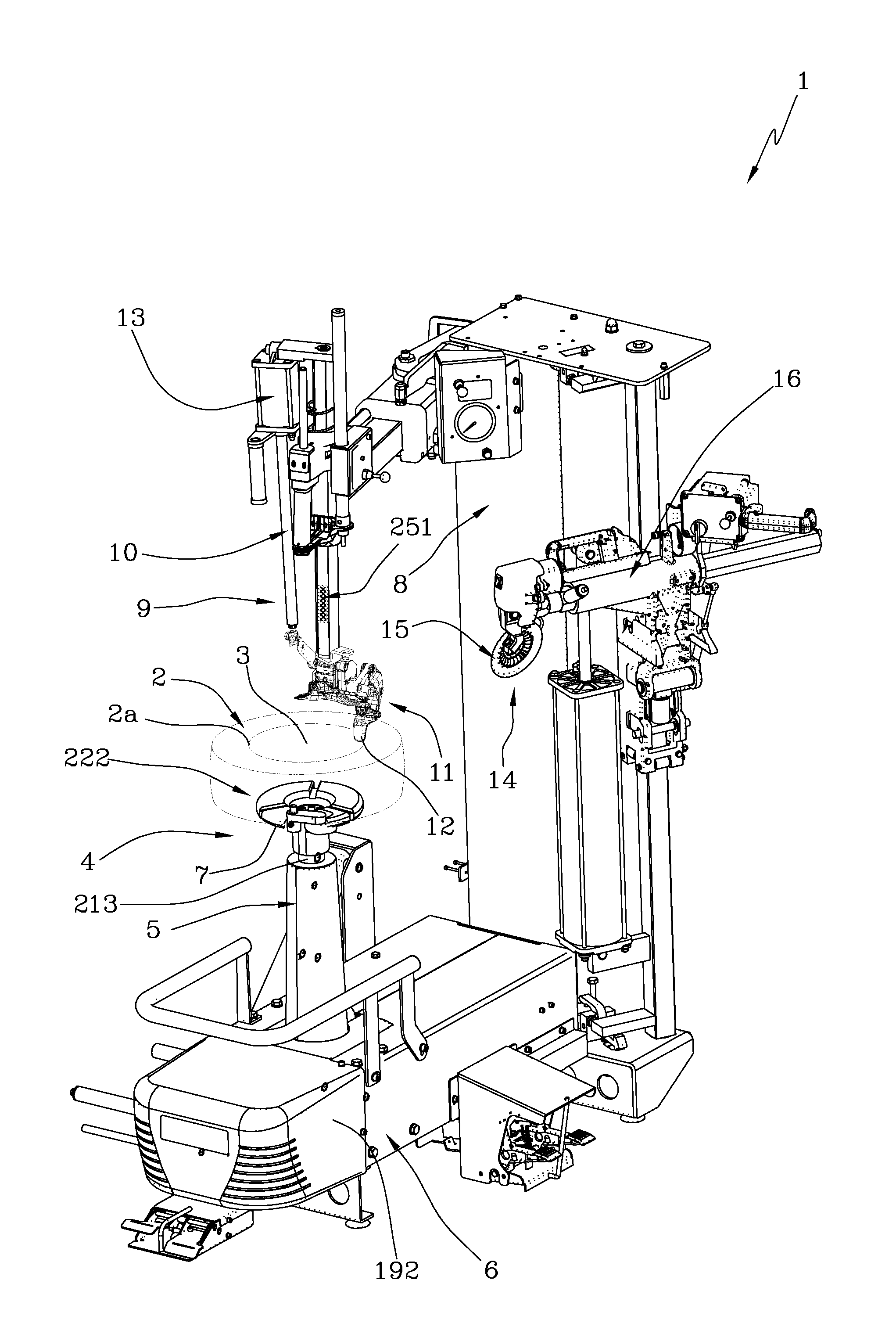
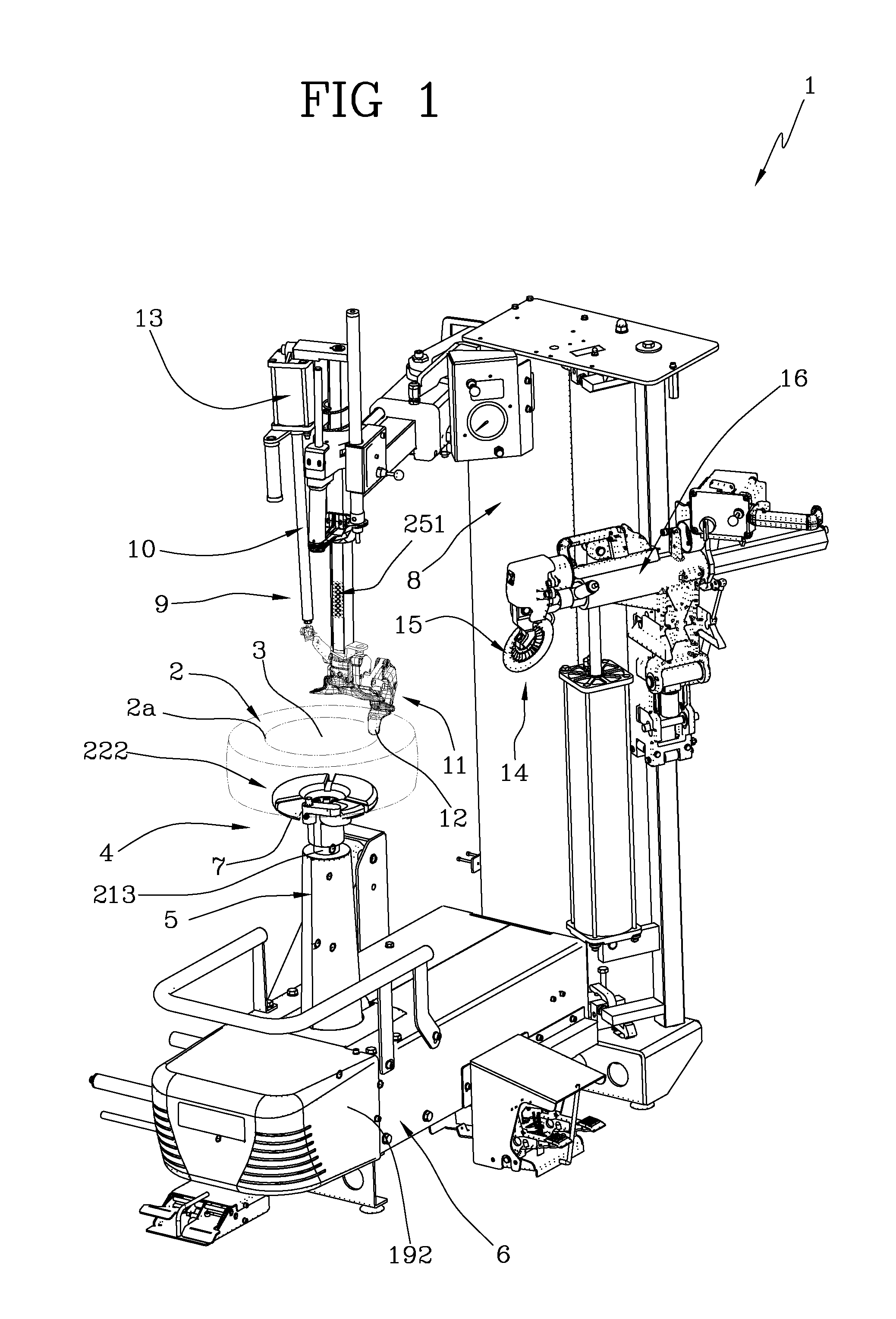
[0065]With reference to the accompanying drawings, the numeral 1 denotes in its entirety an apparatus for mounting and removing tyres 2 on and from respective wheel rims 3.

[0066]The apparatus 1 comprises means 4 for supporting and moving a rim 3, designed to hold the rim 3 to the apparatus 1 and to drive it rotationally about its longitudinal axis.

[0067]In light of this, the supporting and movement means 4 comprise a rim 3 rotation member 171 for turning the rim 3 and the tyre 2 about said longitudinal axis.

[0068]More in detail, the supporting and movement means 4 comprise a rotary shaft 213 extending (vertically in the example illustrated but horizontally in other possible embodiments) from a base 6 and operatively connected to the rotation member 171 housed in the base 6.

[0069]At the top of the shaft 213 there extends a self-centering device 222 in the form of a plate 7 for coupling to a rim 3, designed to anchor the rim 3 (that is, the wheel) to the apparatus 1 and operatively co...


PUM

PropertyMeasurementUnit
mechanical strainaaaaaaaaaa
mechanical stressaaaaaaaaaa
bending strainaaaaaaaaaa

Abstract

An apparatus (1) for mounting and removing a tire (2) on and from a respective rim (3) comprises: a movement element (9) for moving a bead (2a) of the tire (2) in order to insert / remove the bead (2a) into / from a respective groove in the rim (3); means (4) for supporting and moving the rim (3), designed to rotationally drive the rim about its longitudinal axis; characterized in that the means (4) for supporting and moving the rim (3) comprise a sensor (252) for measuring the mechanical strain applied to the supporting and movement means (4) as a result of the mechanical stress on the bead (2a) of the tire (2) during mounting / removal of the latter on / from the rim (3).

Description

BACKGROUND OF THE INVENTION[0001]This invention relates to an apparatus and a method for mounting and removing tyres on and from respective wheel rims.[0002]As is known, apparatuses for mounting and removing tyres on and from respective wheel rims are equipped with a rim supporting element that is suitably power driven to turn the rim during mounting or removal of the tyre.[0003]Usually, the rim supporting element is positioned with its axis vertical (that is, directed substantially in the direction of application of the weight force) or, alternatively, with the axis horizontal.[0004]It should be noted that this invention relates to machines for mounting (and removing) the tyres, without any limitation as to the orientation of the supporting element.[0005]For brevity and simplicity, however, this description will refer to the case where the supporting element is positioned with its axis vertical in such a way as to turn the wheel about a longitudinal axis of rotation oriented along ...

Claims


Application Information

Patent Timeline
Patent Type & Authority Patents(United States)
IPC IPC(8): B60C25/00
CPCB60C25/138B60C25/056B60C25/14Y10T29/49494
Inventor CORGHI, GIULIO
Owner NEXION SPA
Why Eureka
Try Eureka