Structure for installing lightning arrester for electric pole

a technology for installing structures and electric poles, which is applied in the installation of lighting conductors, emergency protective arrangements for limiting excess voltage/current, and connection to earth, etc. it can solve the problems of increasing the number of parts on the upper end of the electric pole, and affecting the safety of users

Inactive Publication Date: 2008-12-18
JEON YOO CHEOR
View PDF8 Cites 17 Cited by
  • Summary
  • Abstract
  • Description
  • Claims
  • Application Information

AI Technical Summary

Benefits of technology

[0009]Accordingly, the present invention has been made keeping in mind the above problems occurring in the prior art, and an object of the present invention is to provide a structure for installing a lightning arrester for an electric pole, in which a lightning arrester, a dead end clamp and an insulator are connected in series, so that electric wires can be arranged in order on the upper end of an electric pole to prevent the upper end of the

Problems solved by technology

Since the electric pole is erected on the ground and supports electric wires in the air, an abnormally high voltage can be formed in the electric wires when a surge such as a thunderbolt is applied thereto.
That is to say, the power line installed on the electric pole and the electric wire for connecting the lightning arrester with the power line are connected with each other by a connector or a sleeve, an insulator for insulation purposes is installed on a cross arm, which is mounted to the electric pole, the lightning arrester is separately erected by a bracket at a different position on the upper end of the electric pole and is tightened along with the insulator by a bolt, and an electric wire extending to the ground is connected to the output portion of the lightning arrester, which is complicated.
In other words, in the conv

Method used


Image

  • Structure for installing lightning arrester for electric pole
  • Structure for installing lightning arrester for electric pole
  • Structure for installing lightning arrester for electric pole

Examples


Embodiment Construction

[0020]Reference will now be made in greater detail to preferred embodiments of the invention, examples of which are illustrated in the accompanying drawings. Wherever possible, the same reference numerals will be used throughout the drawings and the description to refer to the same or like parts.

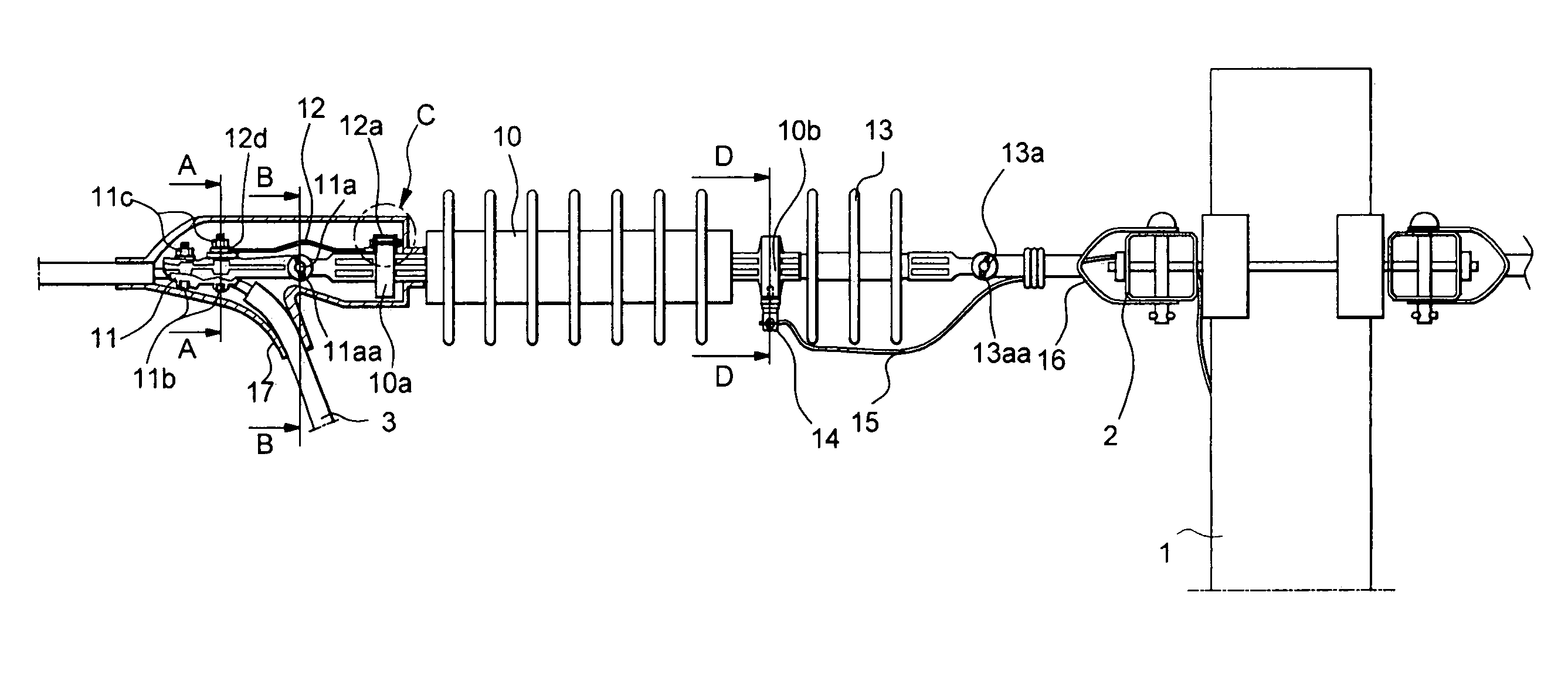
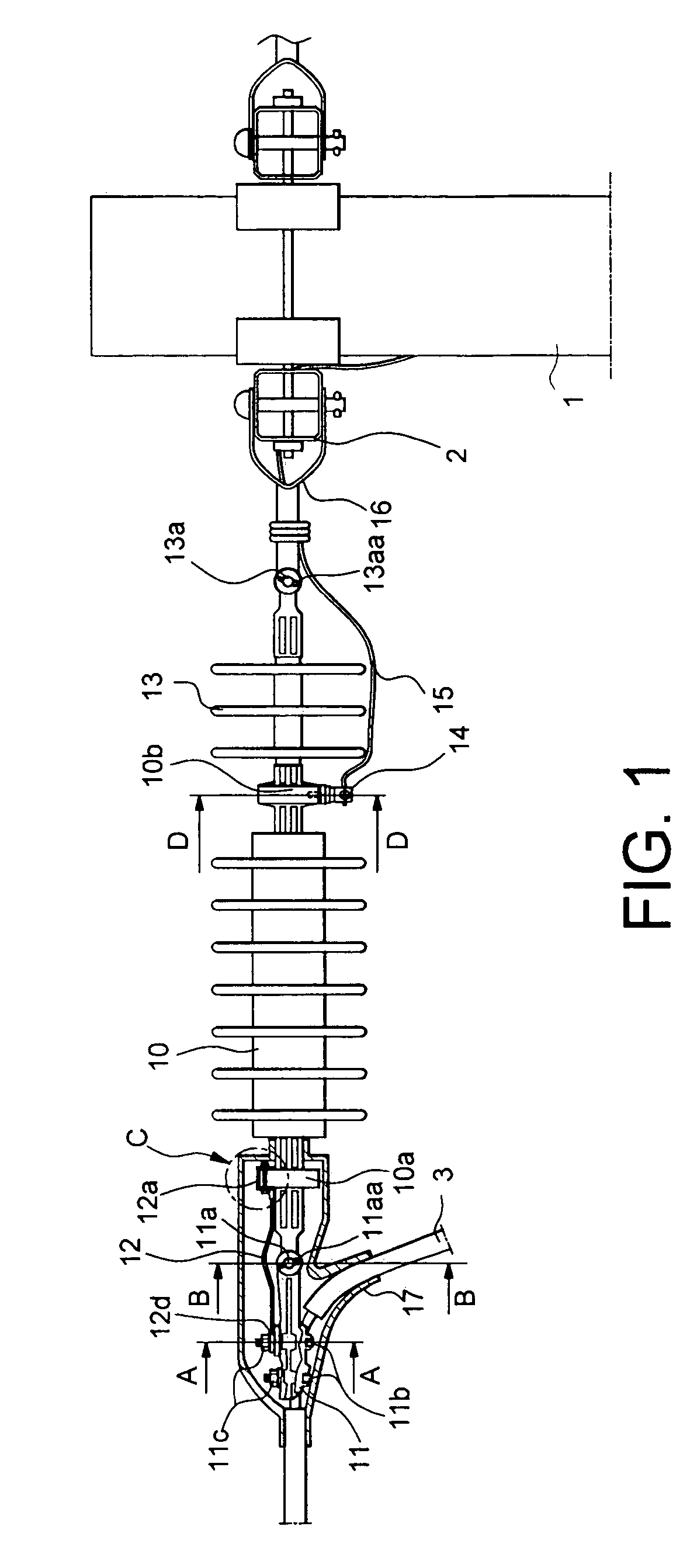
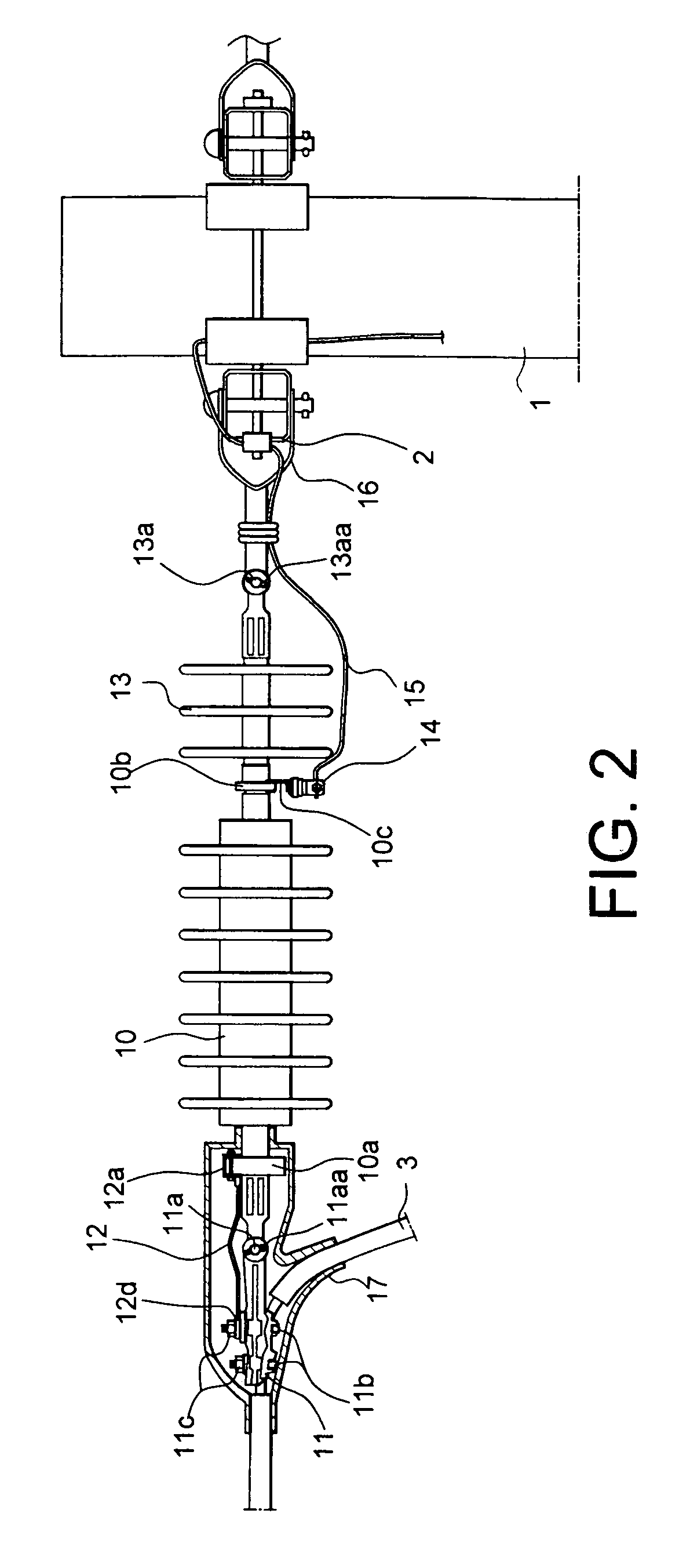
[0021]FIG. 1 is a front view illustrating a structure for installing a lightning arrester for an electric pole in accordance with an embodiment of the present invention. A lightning arrester 10 is configured such that it is installed between the cross arm 2, mounted to an electric pole 1, and a power line 3.

[0022]In the installation structure according to the present embodiment, the lightning arrester 10, a dead end clamp 11, a connection wire 12, and an insulation reinforcing insulator 13 are connected in series. In particular, the lightning arrester 10 and the insulation reinforcing insulator 13 are integrally formed with each other.

[0023]The lightning arrester 10 has a voltage inlet porti...


PUM


Abstract

A structure for installing a lightning arrester between the cross arm mounted to the upper end of an electric pole and a power line is disclosed. A dead end clamp, the lightning arrester and an insulation reinforcing insulator are connected in series, an end of the insulation reinforcing insulator is connected to the cross arm by a shackle, a disconnector is connected to the voltage outlet portion of the lightning arrester, a grounding wire for diverting abnormal voltage to the ground is connected to the disconnector, and an insulation cover surrounds the dead end clamp and the voltage inlet portion of the lightning arrester.

Description

BACKGROUND OF THE INVENTION[0001]1. Field of the Invention[0002]The present invention relates to a structure for installing a lightning arrester for an electric pole and, more particularly, to a structure for installing a lightning arrester for an electric pole, in which a lightning arrester, a dead end clamp and an insulator are connected in series, so that electric wires can be arranged in an orderly manner on the upper end of an electric pole to prevent the upper end of the electric pole from being in disorder and electrical failure from occurring due to the contact of electric wires with foreign objects such as birds, creatures or a magpie nest, installation work can be conveniently conducted to reduce the installation cost and the maintenance and repair fee, and the number of parts to be installed together with the lightning arrester can be decreased to thus reduce the material cost.[0003]2. Description of the Prior Art[0004]As is well known in the art, an electric pole is empl...

Claims


Application Information

Patent Timeline
IPC IPC(8): H02H1/04
CPCH02G7/056H02G13/00H02G13/80H02G13/40
Inventor JEON, YOO CHEOR
Owner JEON YOO CHEOR
Why Eureka
Try Eureka