Restrained, reverse multi-pad bearing assembly

a multi-pad bearing and bearing assembly technology, applied in the direction of bearings, shafts and bearings, rotary bearings, etc., can solve the problems of limited relative foil movement, unidirectional and overlap of foils, limited utilization of such bearings for high-speed rotating machinery, etc., to reduce inconsistencies in foil assemblies, eliminate looseness of foil assemblies, and improve design control

Inactive Publication Date: 2008-12-18
R & D DYNAMICS
View PDF30 Cites 33 Cited by
  • Summary
  • Abstract
  • Description
  • Claims
  • Application Information

AI Technical Summary

Benefits of technology

[0019]The present invention provides greater control over the design of the foil subassemblies during manufacturing, and more particularly, during installation of each foil subassembly into respective channels, so a

Problems solved by technology

Moreover, the foils are typically unidirectional and overlapping.
Generally, coulomb damping, which is required to suppress whirl of the rotating member, is low for such multi-pad bearings, and the low damping levels have limited the utilization of such bearings for high-speed rotating machinery.
This limited relative foil movement contributes to the low coulomb damping characteristic of these multi-pad bearings.
This results in a high preloading on the shaft and thereby requires a high starting torque for the rotating shaft.
Such high starting torque is, of course, disadvantageous as it stresses the machinery being used to drive the shaft and may be severe enough to result in inability to start the engine or motor driving the shaft and/or cause wear or damage to the engine, motor or other drive components.
The tight grip of the bearing foil in the shaft also makes the foil susceptible to rotational deflection and slipping during start up and operation of the rotating shaft.
However, because the foils are a single-pad type, and thus are supported at only one end thereof, exten

Method used


Image

  • Restrained, reverse multi-pad bearing assembly
  • Restrained, reverse multi-pad bearing assembly
  • Restrained, reverse multi-pad bearing assembly

Examples


Embodiment Construction

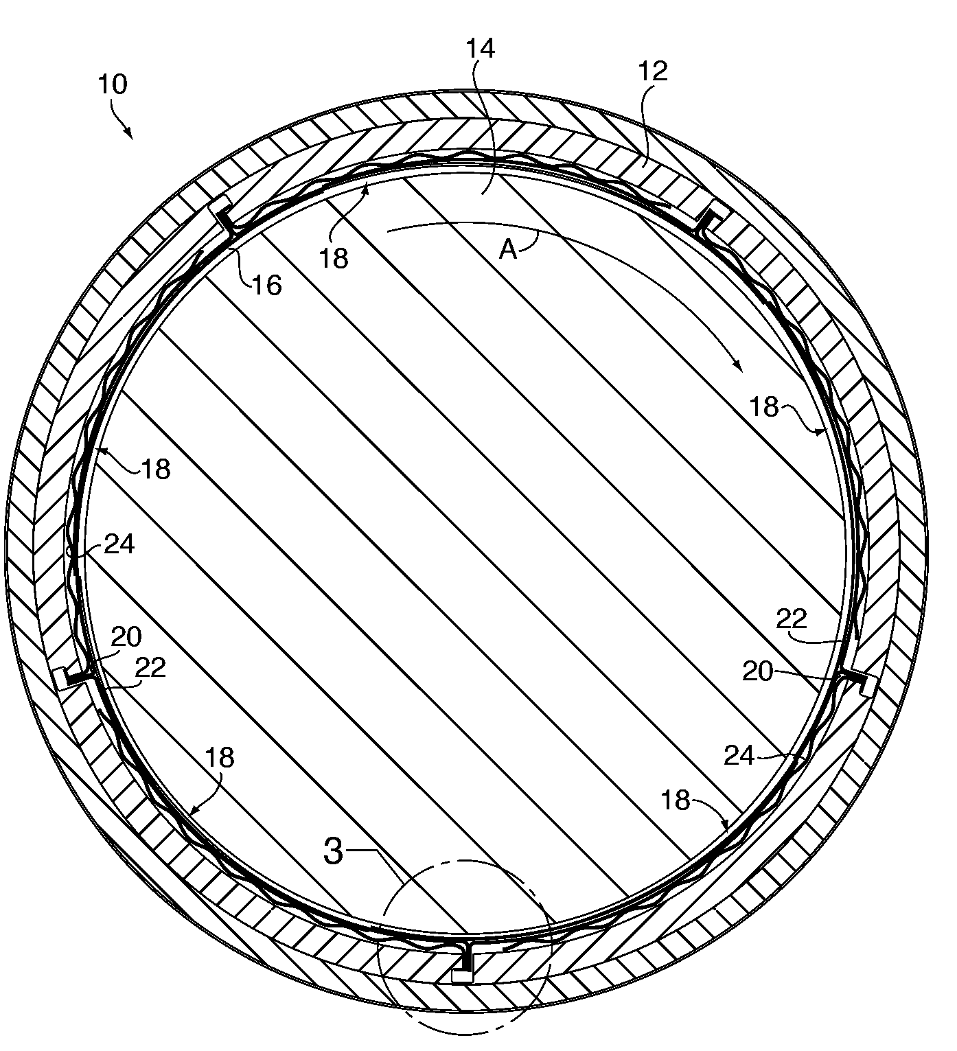
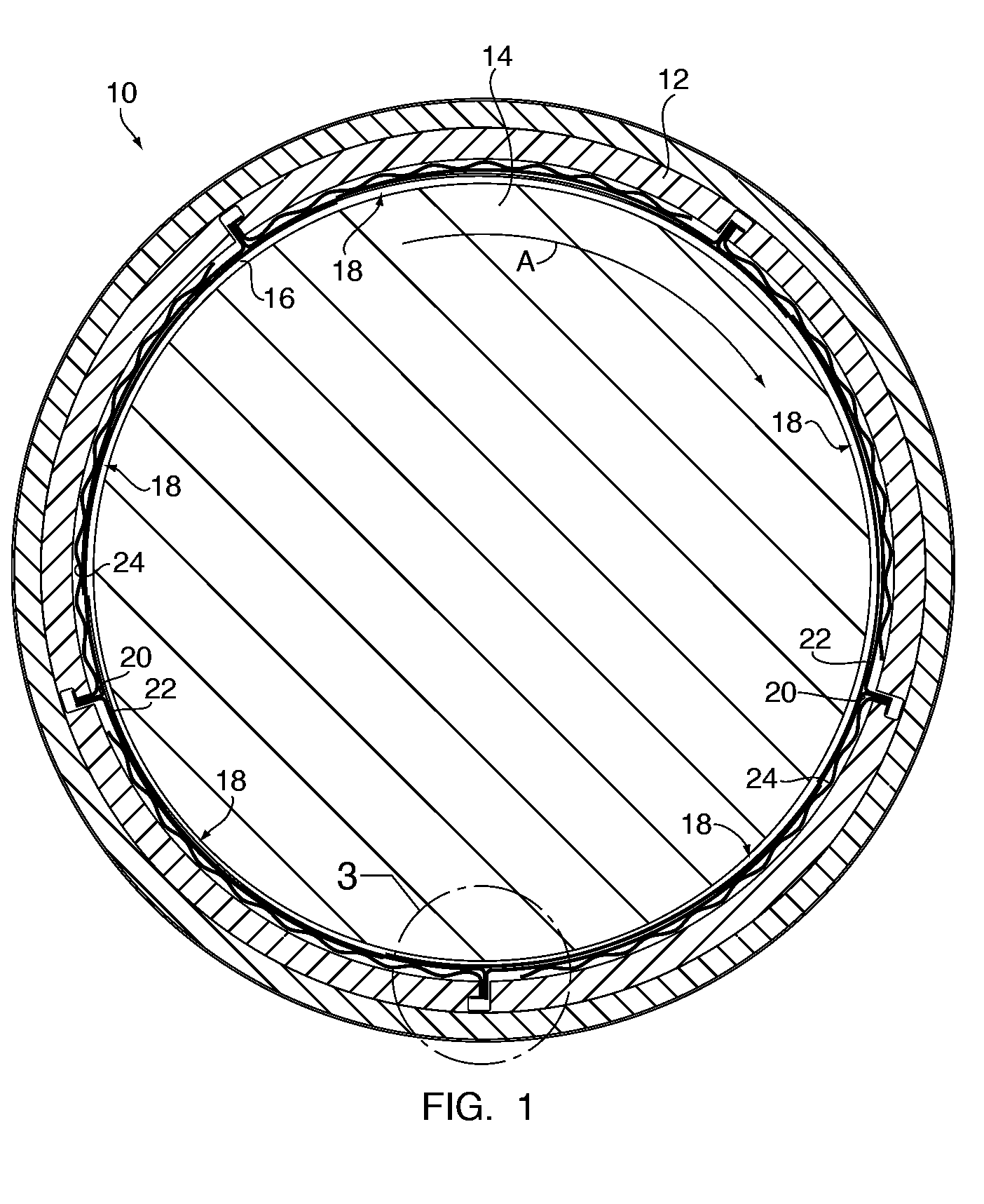
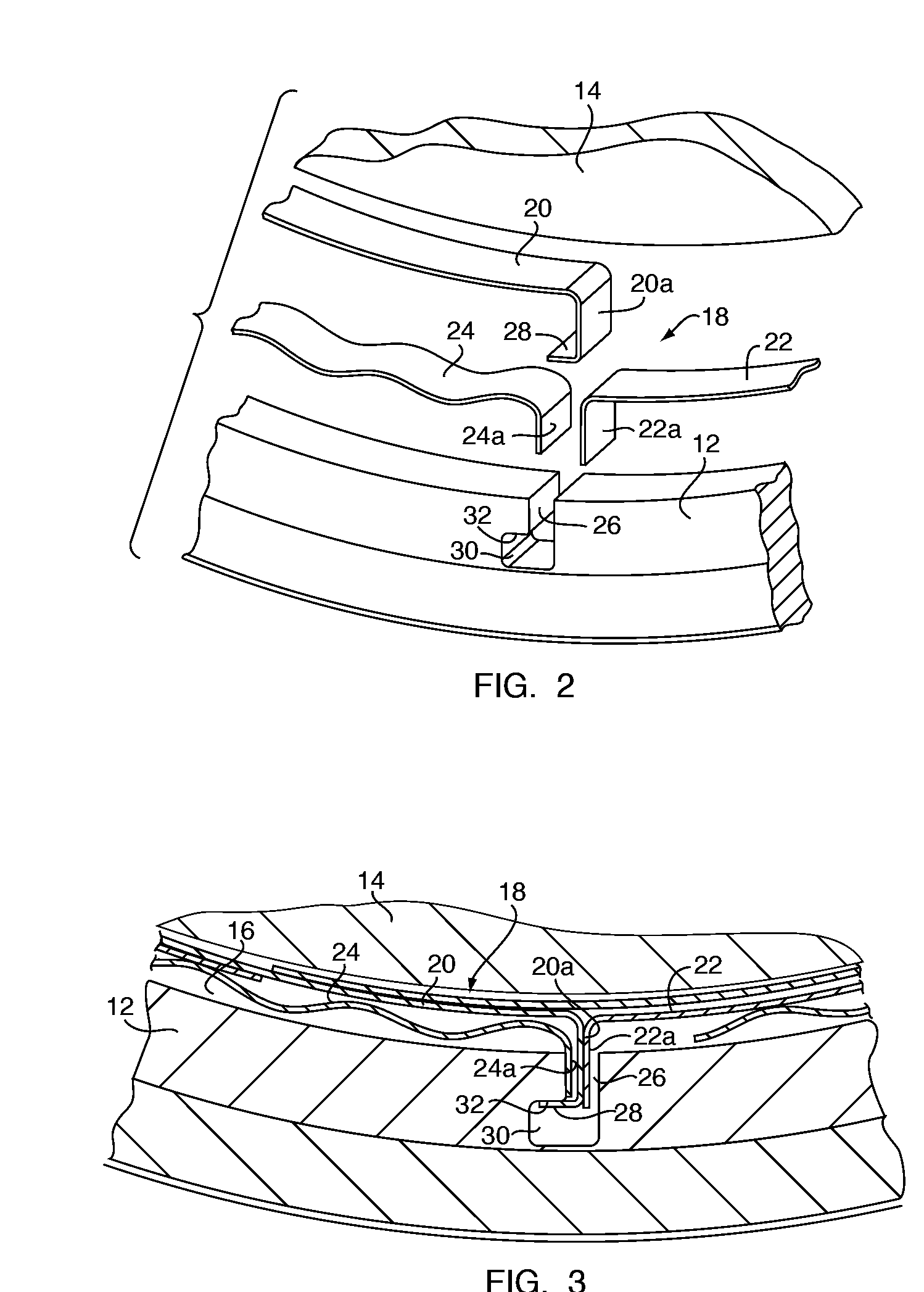
[0025]A goal of the present invention is to design a foil bearing assembly that can be kept loaded at a desired level to maintain the desired compliancy of the foil elements during operation. In order to achieve this goal, the bearing assembly must avoid undesirable radial deflection, rotational slipping, and telescoping within a stationary retaining member. Radial deflection, or “pop up”, of one or more foils due to, for example, whirl of the shaft or imbalanced loading of the bearing assembly, compromises compliancy of the foils and thus affects the operation and efficiency of the system. Accordingly, the present invention relates to a hydrodynamic fluid film bearing assembly of the reverse multi-pad design with features designs to prevent radial deflection, rotational slipping and telescoping within a stationary retaining member, shown generally in FIGS. 1-3. Indeed, the features of the present invention relates to a “restrained reverse multi-pad bearing” design that overcomes th...


PUM


Abstract

A hydrodynamic fluid film bearing assembly has a stationary retaining member defining a central opening and having an inner surface lined by a foil assembly comprised of a plurality of foil subassemblies. Each foil subassembly comprises a first compliant foil, a second compliant foil, and a spring foil, and subtending a rotational segment, less than all, of the inner surface of the retaining member. The complaint foils and the spring foil of each foil subassembly are held within the retaining member in such a way that sliding travel of one compliant foil along the inner surface of the opening is in the opposite rotational direction of sliding travel of the other compliant foil and the spring foil. The foil subassemblies may be restrained from undesired movement during operation by a retention tab extending from the foil subassembly which engages a channel and recess feature formed in the retaining member.

Description

CROSS-REFERENCE TO RELATED APPLICATION [0001]This application claims the benefit of U.S. Provisional Application No. 60 / 944,582, filed Jun. 18, 2007, which is incorporated herein by reference.FIELD OF THE INVENTION [0002]The field of the present invention relates generally to hydrodynamic fluid film bearings and, more particularly, to bearing assemblies employing a plurality of thin foils lining the inner surface of a retaining member within which a high-speed rotating shaft is receivable, to establish and maintain a lubricating fluid film, e.g., air, between the foils and the rotating shaft.BACKGROUND OF THE INVENTION [0003]Recent efforts have been made to improve bearings for high-speed rotating machinery, such as gas turbines for aircraft engines, missile engines or power generation (auxiliary power units). Such efforts have led to the development of various designs for fluid film hydrodynamic bearings. Generally, fluid film hydrodynamic bearings have been successfully employed i...

Claims


Application Information

Patent Timeline
IPC IPC(8): F16C32/06
CPCF16C17/024F16C43/02
Inventor AGRAWAL, GIRIDHARI L.ACCOMAZZO, THOMAS A.BROPHY, MICHAEL
Owner R & D DYNAMICS
Why Eureka
Try Eureka