Cross shaft member and cross shaft joint with the same

a cross shaft member and cross shaft joint technology, applied in the field of cross shaft members, can solve the problems of not meeting the above requirements and increasing the weight achieve the effects of increasing the static strength of the cross shaft member, increasing the weight, and increasing the weigh

Inactive Publication Date: 2008-12-18
JTEKT CORP
View PDF3 Cites 0 Cited by
  • Summary
  • Abstract
  • Description
  • Claims
  • Application Information

AI Technical Summary

Benefits of technology

[0011]In the cross shaft member of the invention, the four ridge-like thickened portions are formed in the recessed portion formed in the body portion, and are equally spaced from one another, and extend at an angle of about 45° relative to the axes of the shaft portions. With this construction, the static strength of the cross shaft member can be greatly increased while keeping a weight increase to a minimum.
[0012]More specifically, the strength of the cross shaft member includes a fatigue strength and a static strength, and this fatigue strength is determined by stresses, and therefore can be adjusted by changing the shape of a neck of each shaft portion, etc. On the other hand, the static strength is less dependent on stresses, and is determined by a size (diameter) of the shaft portions and a volume of the body portion (i.e., a cross-sectional area of the body portion), and therefore in order to increase the static strength, it is necessary to increase the weight of the cross shaft member and particularly the weight of the body portion. In this connection, the inventor of the present invention has made an extensive study, and has found that what contributes to the increased static strength of the cross shaft member is not the overall volume of the body portion, but is the size of a cross-sectional area of the body portion through a plane disposed at an angle of about 45° relative to the axes of the shaft portions. Therefore, the four equally-spaced ridge-like thickened portions, extending at an angle of about 45° relative to the axes of the shaft portions, were formed in the recessed portion, and by doing so, the static strength of the cross shaft member could be greatly increased with a minimum weight increase. Particularly when a height of the ridge-like thickened portions is made generally equal to a height of brim portions (of a brim of the body portion surrounding the recessed portion) directly extending respectively to the ridge-like thickened portions, a static strength generally equal to that obtained when the recessed portion is not provided can be secured.
[0013]In the cross shaft member of the present invention, the static strength thereof can be greatly increased with a minimum weight increase, so that the static strength of the cross shaft joint is greatly increased.

Problems solved by technology

In this case, however, the weight of the cross shaft member much increases, and this can not meet the above requirement of the lightweight design.

Method used


Image

  • Cross shaft member and cross shaft joint with the same
  • Cross shaft member and cross shaft joint with the same
  • Cross shaft member and cross shaft joint with the same

Examples


Embodiment Construction

[0021]A preferred embodiment of a cross shaft member of the present invention will now be described in detail with reference to the accompanying drawings.

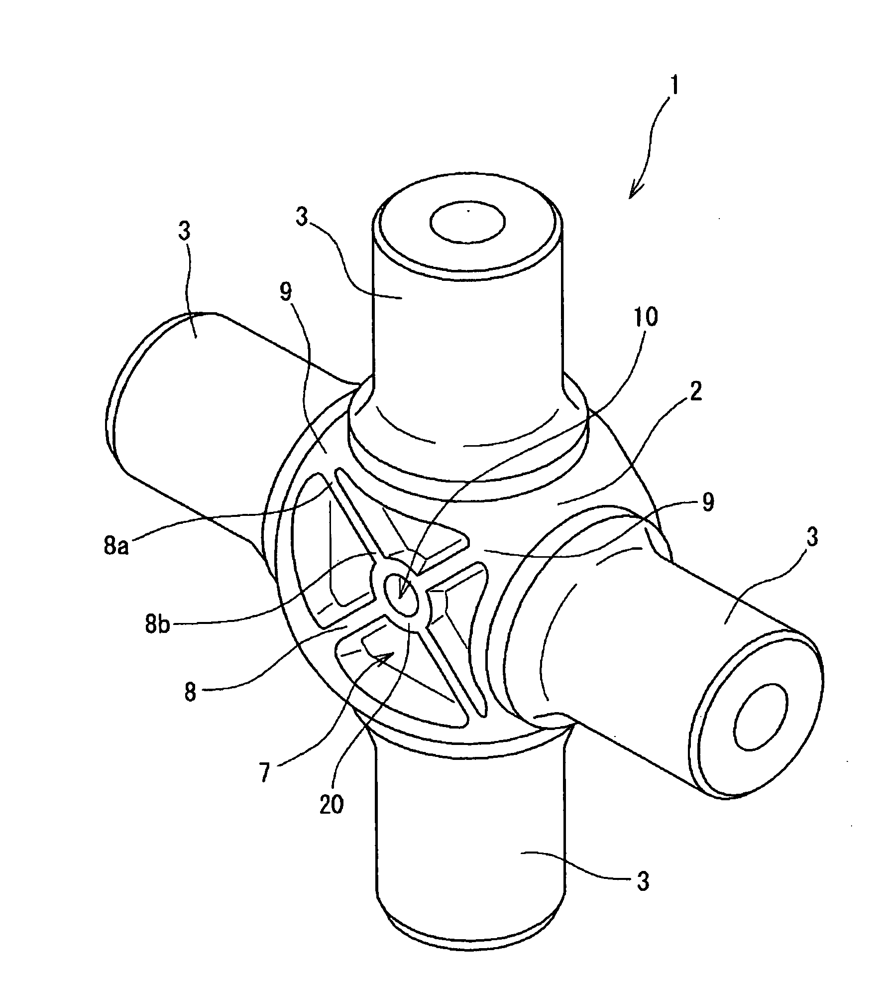
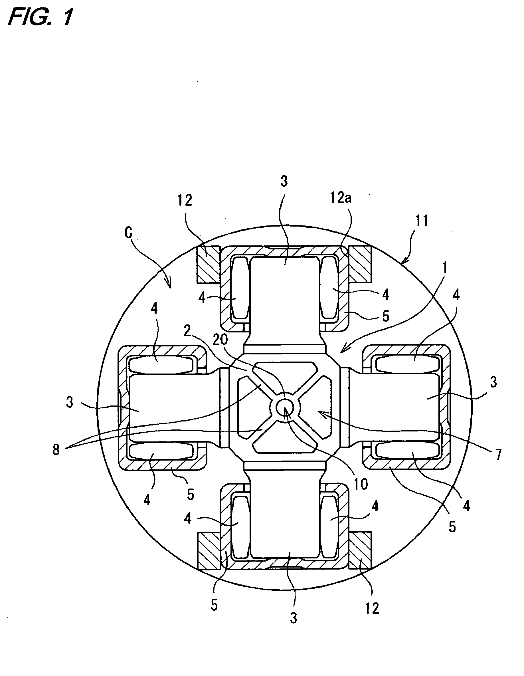
[0022]FIG. 1 is a partly cross-sectional, front-elevational view of a cross shaft joint C provided with one preferred embodiment of the cross shaft member 1 of the invention. This cross shaft joint C comprises the cross shaft member 1 having four shaft portions 3 arranged in a generally cross-shape on an outer periphery of a body portion 2 thereof, a plurality of (circular) rows of cylindrical rollers (rolling elements) 4 provided respectively around the shaft portions 3, and bearing cups 5 rotatably mounted respectively on the shaft portions 3 through the respective rows of cylindrical rollers 4. In FIG. 1, only the bearing cups 5 and yokes 12 (described later) are shown in cross-section for the better understanding.

[0023]The cross shaft joint C is connected via yoke members 11 in a torque-transmitting manner to each end of a prop...


PUM


Abstract

A cross shaft member has four shaft portions arranged in a generally cross-shape around an outer periphery of a body portion thereof, and a recessed portion is formed in the body portion, and has a depth in a direction perpendicular to a plane in which axes of the four shaft portions lie. Four ridge-like thickened portions are formed in the recessed portion, and are equally spaced from one another, and extend diagonally with respect to the axes of the shaft portions in the plane.

Description

BACKGROUND OF THE INVENTION[0001]1. Field of the Invention[0002]This invention relates to a cross shaft member. More specifically, the invention relates to a cross shaft member for forming a cross shaft joint (universal joint) used in a propeller shaft, an intermediate shaft of a vehicular steering apparatus or the like.[0003]2. Related Art[0004]In a vehicular steering apparatus, etc., a cross shaft joint has been used for interconnecting two shafts (not disposed on a common axis) in a torque-transmitting manner. This cross shaft joint comprises a cross shaft member having four shaft portions arranged in a generally cross-shape on an outer periphery of a body portion thereof, a plurality of rows of cylindrical rollers (rolling elements) provided respectively around the shaft portions, and bearing cups (outer rings) mounted respectively around the rows of cylindrical rollers, an outer peripheral surface of each shaft portion being used as an inner ring raceway surface for the cylindr...

Claims


Application Information

Patent Timeline
Patent Type & Authority Applications(United States)
IPC IPC(8): F16D3/205
CPCF16D3/41
Inventor MIZUNO, KOICHIRO
Owner JTEKT CORP
Why Eureka
Try Eureka