Instrumentation and associated techniques for minimally invasive spinal construct installation

a technology of vertebral connecting elements and instruments, which is applied in the field of spinal fixation surgery, can solve the problems of threatening critical elements, affecting the recovery of patients, so as to promote post-surgery patient recovery, improve efficiency and accuracy, and minimize the effect of invasiveness

Inactive Publication Date: 2008-12-18
ZIMMER SPINE INC
View PDF21 Cites 85 Cited by
  • Summary
  • Abstract
  • Description
  • Claims
  • Application Information

AI Technical Summary

Benefits of technology

[0015]The various embodiments of this invention enable the surgeon to install the spinal fixation construct with smaller discrete incisions as opposed to an extended incision. As such, a more minimally invasive surgical procedure can be accomplished with this invention thereby promoting post-surgery patient recovery. As a result of these and other aspects of this invention, increased efficiency and accuracy is provided for installation of a spinal fixation construct in a minimally invasive atmosphere thereby promoting patient recovery and optimum spinal surgery results.

Problems solved by technology

Patients that suffer from such conditions usually experience extreme and debilitating pain as well as diminished range of motion and nerve function.
These spinal disorders may also threaten the critical elements of the nervous system housed within the spinal column.
In combination with the relatively long incision typically required for the installation of the fixation construct, extended surgical procedures and related difficulties may lead, for example, to extended patient recovery.

Method used


Image

  • Instrumentation and associated techniques for minimally invasive spinal construct installation
  • Instrumentation and associated techniques for minimally invasive spinal construct installation
  • Instrumentation and associated techniques for minimally invasive spinal construct installation

Examples


Embodiment Construction

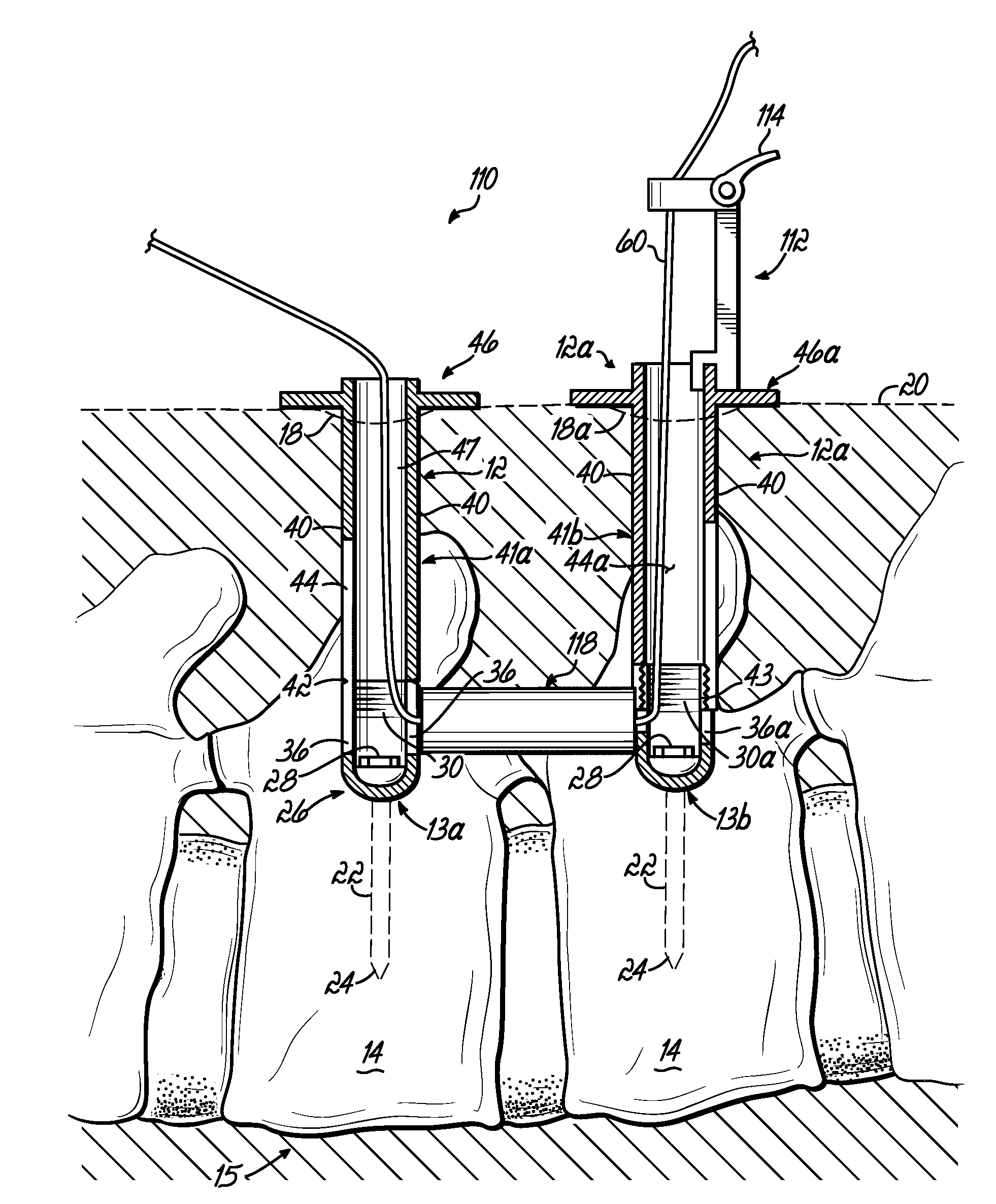
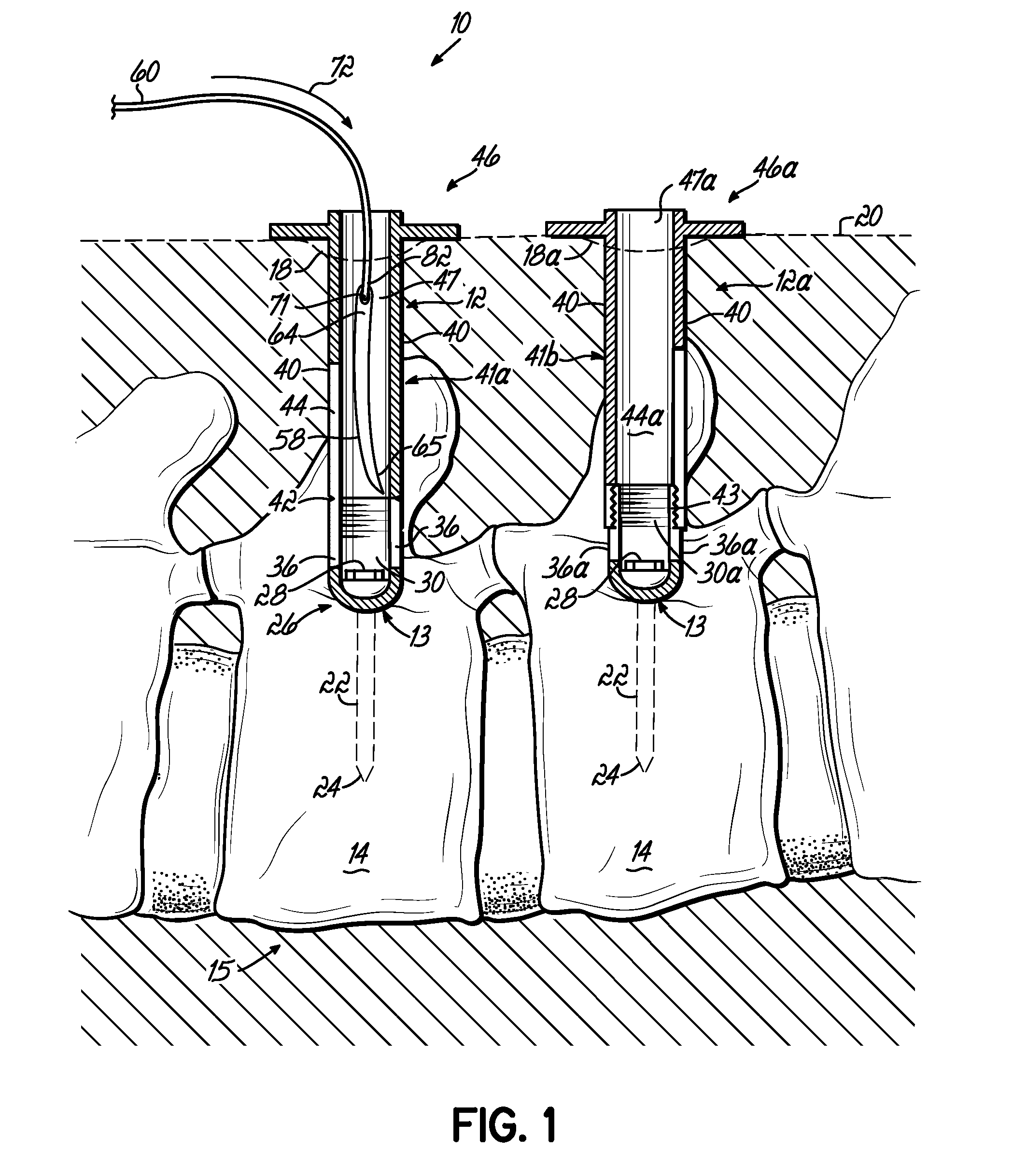
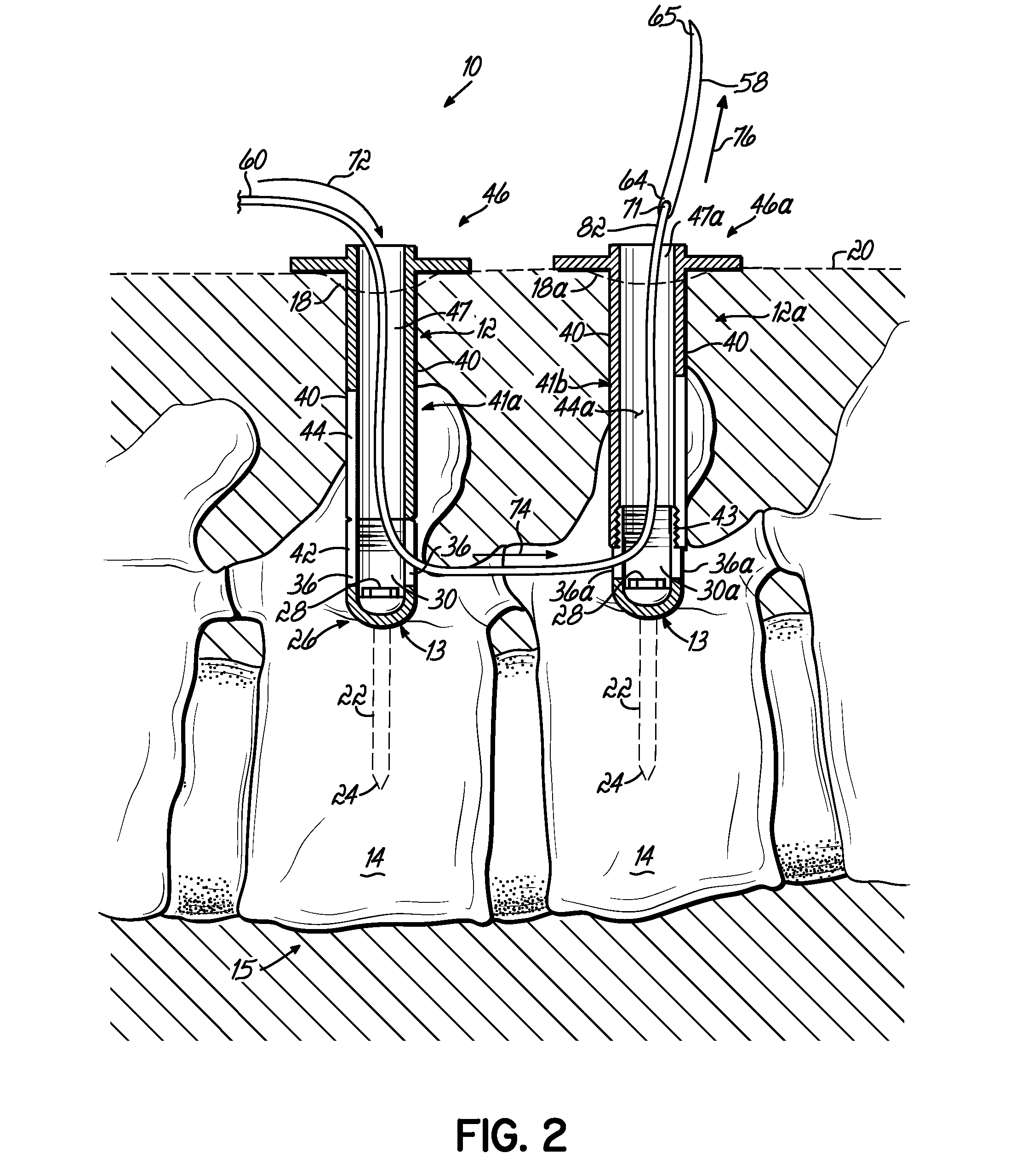
[0025]Referring to the drawings, various components and tools are shown to enable a minimally invasive surgery to install a spinal fixation system. In FIGS. 1-5, an exemplary spinal fixation system 10 includes a number of bone anchors 12, 12a that, in one embodiment, are each pedicle screw assemblies, each of which is inserted into selected vertebrae 14 of a patient. The pedicle screw assemblies 12, 12a are joined together in the spinal fixation system by a connecting element which in one embodiment is a spine rod 16. The connecting element may be a rigid rod or alternatively something other than a rigid rod, such as a flexible connecting element. For ease of understanding, the connecting member is hereinafter referred to as “spine rod 16.”

[0026]Each of the pedicle screw assemblies 12, 12a may be inserted into the patient through discrete and often individual incisions 18 in the patient's skin 20. In certain instances, a single incision 18 may be available to provide installation of...


PUM


Abstract

A spinal fixation installation assembly includes an elongate member having a trailing end. The elongate member, which could be a rigid member, is configured for travel in a first direction along an elongate portion of a first bone anchor coupled to a spine. The elongate member is also configured to travel in a second direction between the first bone anchor and a second bone anchor also coupled to the spine. A cord member is coupled to the trailing end of the elongate member. In one aspect of this embodiment, a spine rod is coupled to the cord member at its leading end and is configured for travel in the first and second directions. The elongate portion of one or more of the bone anchors may extend percutaneously from the spine, while the spine rod may be releasably coupled to the cord member.

Description

FIELD OF THE INVENTION[0001]This invention relates generally to spinal fixation surgery and more specifically relates to instrumentation and associated techniques for minimally invasive installation of vertebral connecting elements of spinal fixation constructs.BACKGROUND[0002]The spinal column is a highly complex system of bones and connective tissues that provides support for the body and protects the delicate spinal flexible connecting member and nerves. The spinal column includes a series of vertebrae stacked one on top of the other, each vertebral body including an inner or central portion of relatively weak cancellous bone and an outer portion of relatively strong cortical bone. An intervertebral disc is situated between each vertebral body to cushion and dampen compressive forces experienced by the spinal column. A vertebral canal containing the spinal cord and nerves is located posterior to the vertebral bodies. In spite of the complexities, the spine is a highly flexible st...

Claims


Application Information

Patent Timeline
Patent Type & Authority Applications(United States)
IPC IPC(8): A61F5/00A61B17/70
CPCA61B17/7085A61B2019/307A61B17/7091A61B2090/037
Inventor HESTAD, HUGH D.KUESTER, W. MATTHEW
Owner ZIMMER SPINE INC
Why Eureka
Try Eureka