Cooler For Transformer Using Generation Cycle

Inactive Publication Date: 2008-12-25
RIM SEONG HWANG
View PDF12 Cites 14 Cited by
  • Summary
  • Abstract
  • Description
  • Claims
  • Application Information

AI Technical Summary

Benefits of technology

[0009]FIG. 5 illustrates the cooler using the generation cycle only the refrigerant boiler and the condenser are installed. It is similar to the FIG. 4 but different that the refrigerant feeding pump 18 that the check valve 19 is installed in parallel is omitted. In this case the liquefied refrigerant from the condenser 16 goes to the refrigerant boiler 13 and a cycle of the cooling transformer is finished. The structure of the cooler becomes very simple.

Problems solved by technology

To adopt the refrigeration cycle that can makes the temperature of the insulation oil be lower than that of the atmosphere in the cooling of the transformer causes over-cooling and increases the probability of the trouble in operation.
In the case of the heat-pipe to maintain the vacuum is very difficult and the small pipe type facilities can not cool the large transformer.

Method used


Image

  • Cooler For Transformer Using Generation Cycle
  • Cooler For Transformer Using Generation Cycle
  • Cooler For Transformer Using Generation Cycle

Examples


Embodiment Construction

[0004]Hereinafter, a preferred embodiment of the present invention will be described in detail with reference to the accompanying drawings.

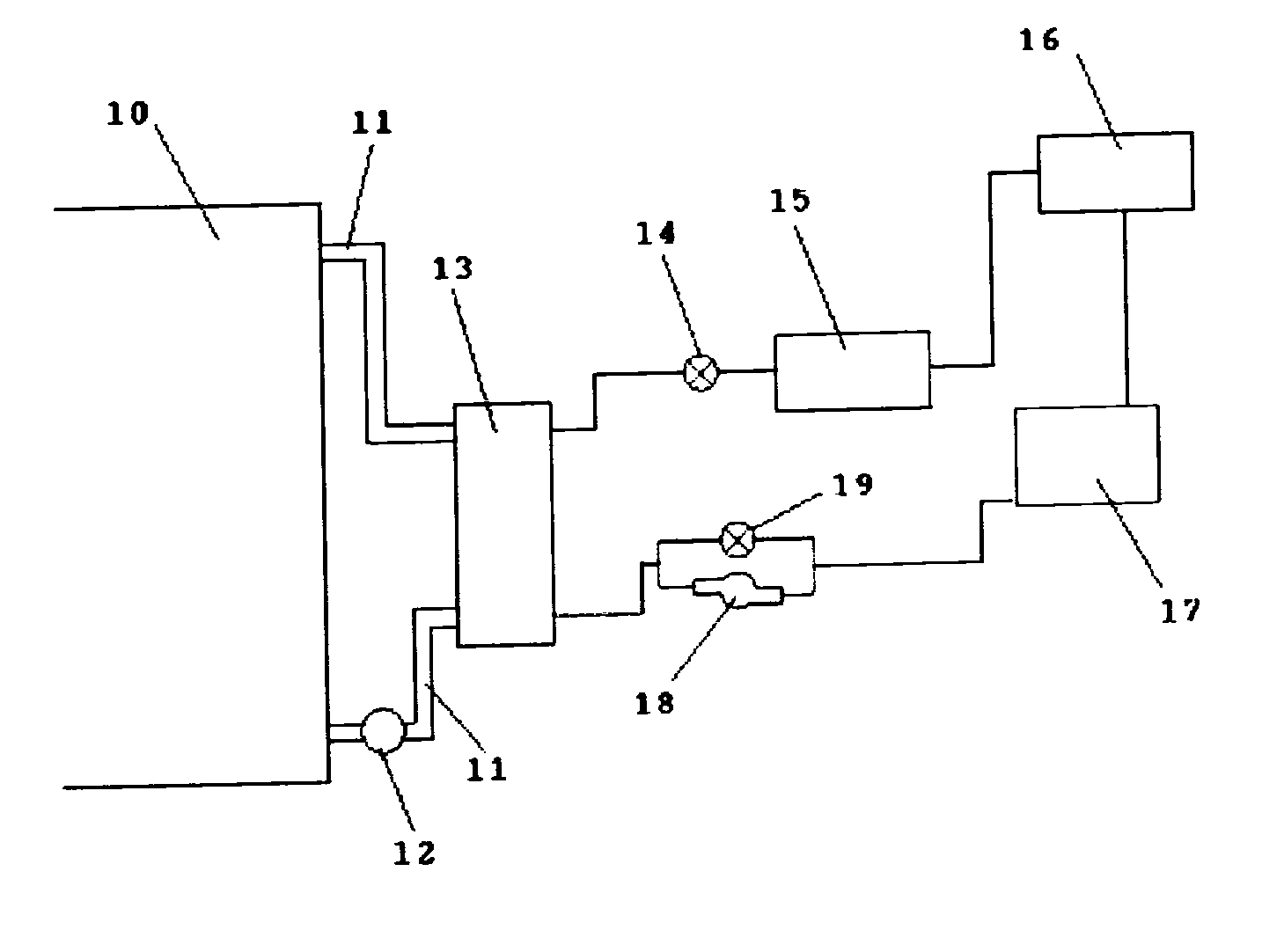
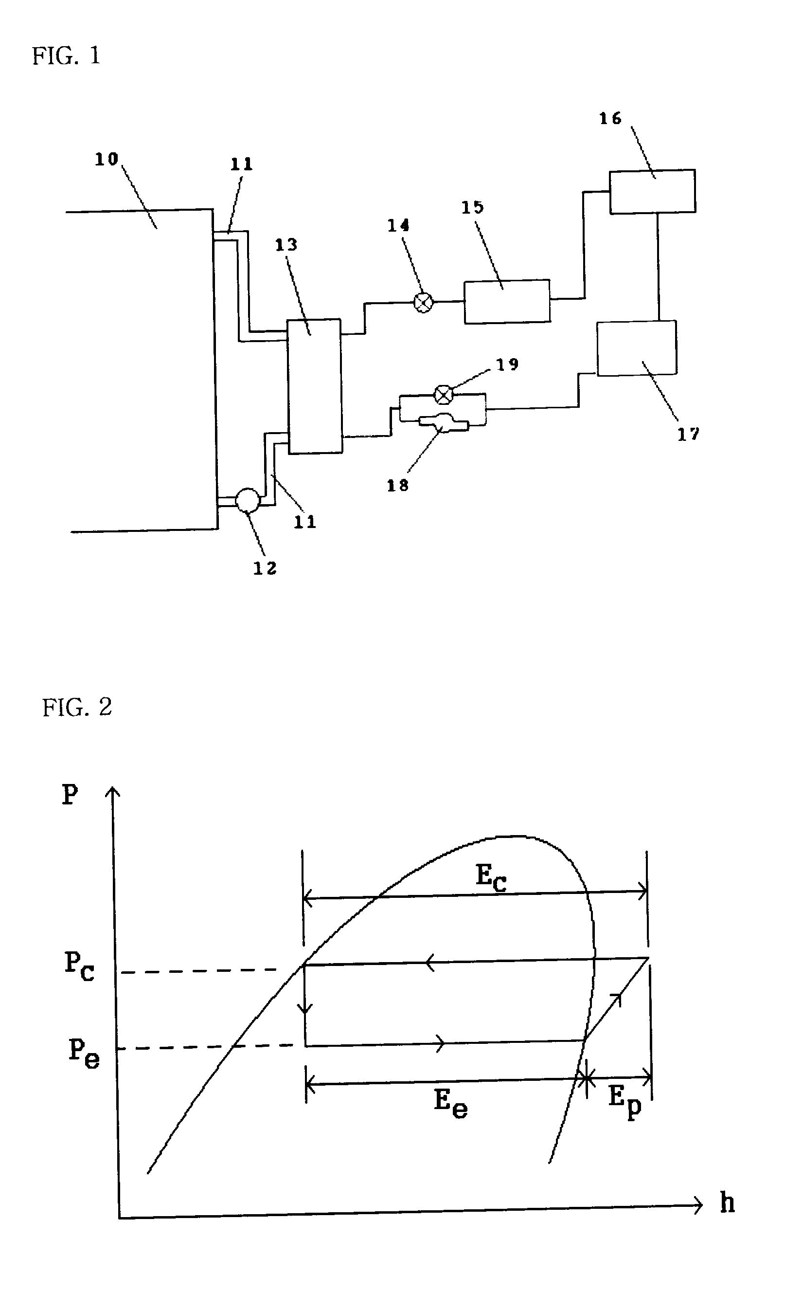
[0005]FIG. 1 illustrates the cooler using the generation cycle adopted in present invention. More than two of the oil circulation pipes 11 are constructed between the transformer body 10 and the refrigerant boiler 13. Minimum one of the oil circulation pump 12 is installed in the line of the oil circulation pipe 11. In this case, the refrigerant boiler 13 is a heat exchanger that the heat exchange between the enforced circulating insulation oil and the refrigerant is executed in. The cycling pipe loop for the refrigerant circulation is constructed in the following sequence; the refrigerant side of the refrigerant boiler 13, the pressure valve 14, the expander 15, the condenser 16, the refrigerant tank 17, the refrigerant feeding pump 18 that the check valve 19 is installed in parallel, the other refrigerant side of the refrigerant boiler 13. The ...


PUM


Abstract

The present invention relates to a cooler for a transformer using a generation cycle to eliminate the heat applied to the transformer. The insulation oil heated in the transformer gasifies the refrigerant in the refrigerant boiler and the insulation oil is cooled by the latent heat of evaporation of the refrigerant. The gasified refrigerant exhausts out the heat in the condenser and it becomes liquefied. The liquefied refrigerant returns to the refrigerant boiler by the refrigerant feeding pump or by gravity. The present invention is very effective with respect to operating cost and reliability.

Description

TECHNICAL FIELD[0001]The present invention relates to the cooler for transformer. The heat applied to the transformer is divided into 2 components. The first is the heat applied from outside of the transformer and the second is the heat of winding loss and core loss that comes in operation of the transformer. These heats give an influence to the temperature of the insulation oil and give an impact to the performance of the winding insulation. And it becomes a key factor of the decision of the capacity and the lifetime of the transformer. We have eliminated the heat applied to the transformer by the cooling methods of ONAN (Natural oil, Natural air cooling), OFAF (Forced oil, Forced air cooling), OFWF (Forced oil, Forced water cooling) and etc. The present invention adopts the generation cycle for the cooling method of the transformer newly.BACKGROUND ART[0002]Some people include I have invented the cooler for the transformer using refrigeration cycle. The refrigeration cycle has the...

Claims


Application Information

Patent Timeline
IPC IPC(8): H01F27/08
CPCF01K25/10F22B1/167F22B3/02H01F27/12H01F27/18
Inventor RIM, SEONG-HWANG
Owner RIM SEONG HWANG
Why Eureka
Try Eureka