
Welding system and method having controlled liner contour and welding wire curvature

Active Publication Date: 2008-12-25
ILLINOIS TOOL WORKS INC
View PDF8 Cites 36 Cited by
  • Summary
  • Abstract
  • Description
  • Claims
  • Application Information

AI Technical Summary

Benefits of technology

[0007]In summary, welding wire having a relatively straight geometry when pulled from a package can result in reduced contact between the weldin

Problems solved by technology

The curvature can cause the welding wire to bind, jam, or flip within the torch.
In either case, the curvature can cause problems within the torch.
Although this relatively straight geometry reduces some problems with binding, jamming, or flipping within the torch, it also causes problems with inconsistent contact between the contact tip and the welding wire.
If the welding wire does not adequately contact the internal passage of the contact tip, then more energy is consumed at the interface between the contact tip and the welding wire, and arcing can occur inside the contact tip leading to undesirable arc damage, deposits, and so forth.
In turn, the contact tip can prematurely wear out and cease to transfer sufficient energy (e.g., current) to the welding wire, thereby decreasing energy transfer between the welding wire and the work piece.
The premature wear can also cause large fluctuations of the welding current and arc stability.
If insufficient energy is transferred to the weld location, then the welding wire may not melt to form the weld and / or the weld may not have the desirable characteristics leading to subsequent failure.
As a result, the welding wire itself can cause premature wear and failure of the contact tip.

Method used


Image

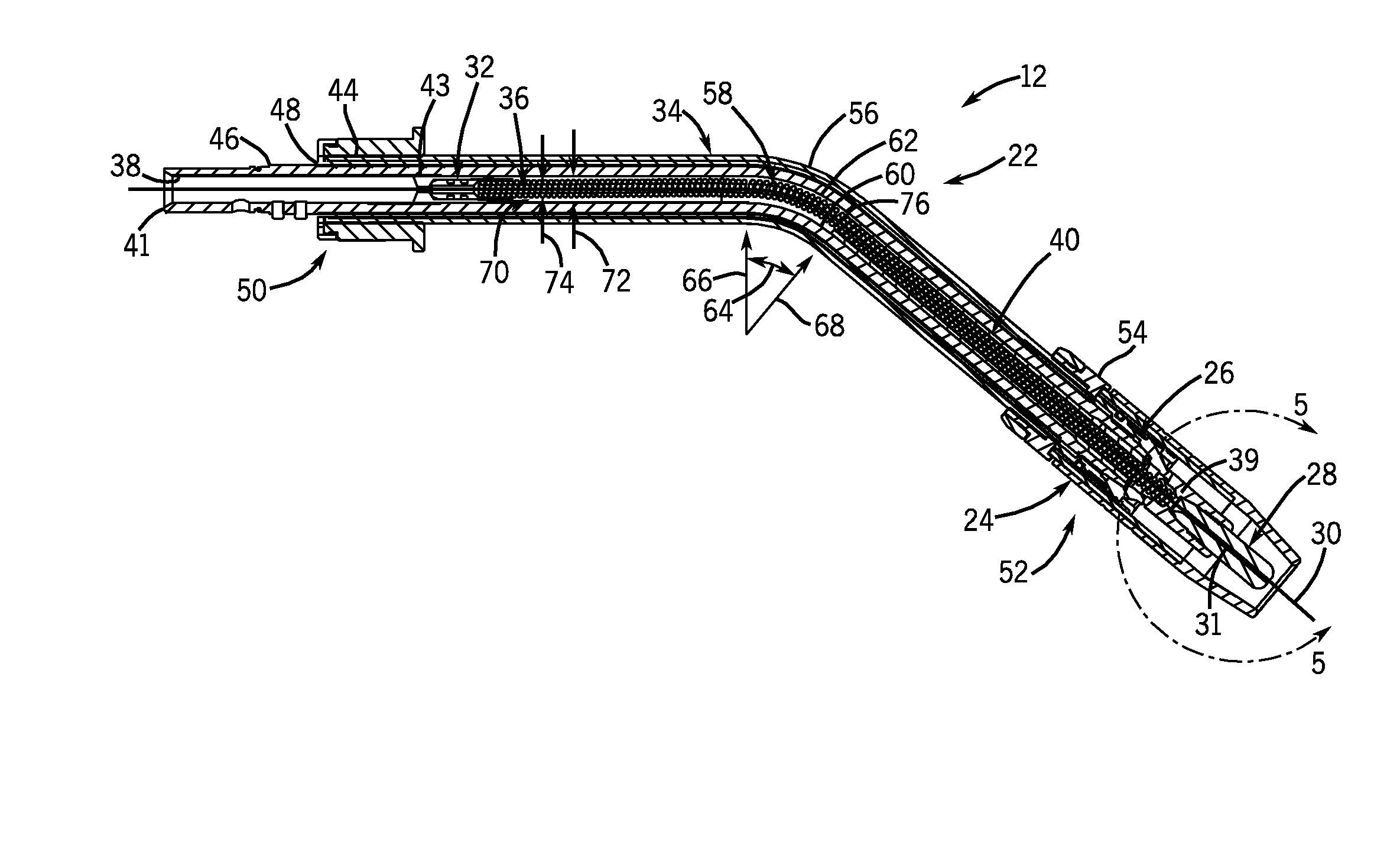
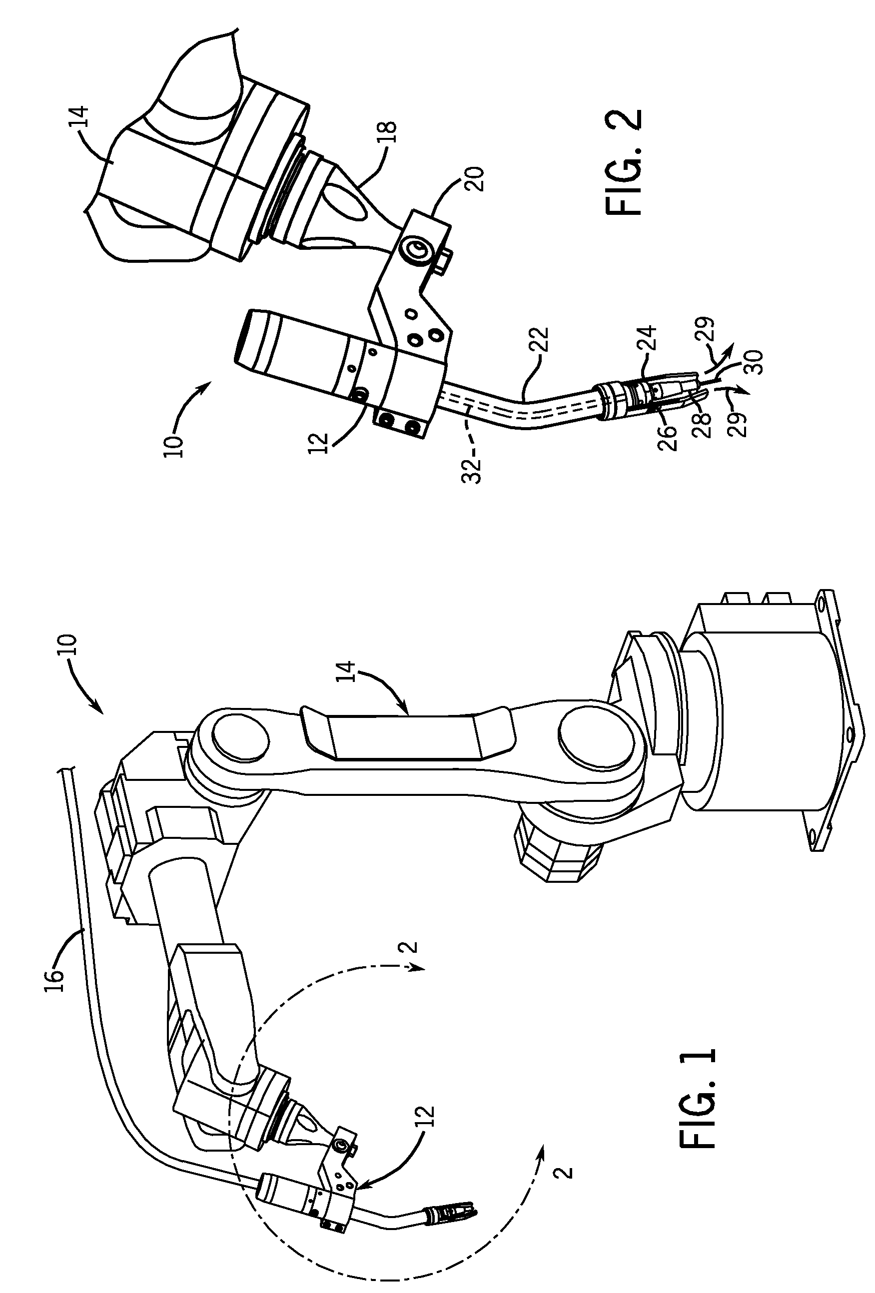
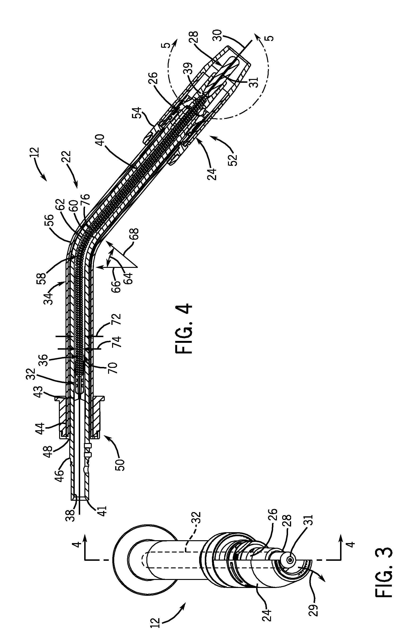
  • Welding system and method having controlled liner contour and welding wire curvature
  • Welding system and method having controlled liner contour and welding wire curvature
  • Welding system and method having controlled liner contour and welding wire curvature

Examples


Embodiment Construction

[0022]One or more specific embodiments of the present invention will be described below. In an effort to provide a concise description of these embodiments, all features of an actual implementation may not be described in the specification. It should be appreciated that in the development of any such actual implementation, as in any engineering or design project, numerous implementation-specific decisions must be made to achieve the developers' specific goals, such as compliance with system-related and business-related constraints, which may vary from one implementation to another. Moreover, it should be appreciated that such a development effort might be complex and time consuming, but would nevertheless be a routine undertaking of design, fabrication, and manufacture for those of ordinary skill having the benefit of this disclosure.

[0023]In various embodiments of a torch, a novel gooseneck assembly is provided to address the need to improve the consistency of the contact between a...


PUM

PropertyMeasurementUnit
Distanceaaaaaaaaaa
Proximity effectaaaaaaaaaa

Abstract

A welding system, in certain embodiments, includes a torch having a neck with an arcuate portion, and a resilient jump liner disposed in the neck and extending through the arcuate portion. The resilient jump liner includes a pathway having a curvature configured to bend a welding wire passing through the pathway. The system also includes an annular support disposed about the resilient jump liner inside the neck, wherein the annular support is configured to at least substantially fix the curvature to force the welding wire to achieve a wire curvature. The system also includes a contact tip coupled to the neck, wherein the wire curvature is configured to bias the welding wire into substantially consistent contact with an interior pathway through the contact tip.

Description

CROSS REFERENCE TO RELATED APPLICATIONS[0001]This application claims priority to U.S. Provisional Patent Application No. 60 / 945,888, entitled “WELDING SYSTEM AND METHOD USING HIGH FREQUENCY / LOW ENERGY GOOSENECK ASSEMBLY”, filed on Jun. 22, 2007, which is herein incorporated by reference in its entirety.BACKGROUND[0002]This section is intended to introduce the reader to various aspects of art that may be related to various aspects of the present invention, which are described and / or claimed below. This discussion is believed to be helpful in providing the reader with background information to facilitate a better understanding of the various aspects of the present invention. Accordingly, it should be understood that these statements are to be read in this light, and not as admissions of prior art.[0003]The invention relates generally to welding systems and, more particularly, to torches having a wire fed to a contact tip.[0004]Existing welding torches, such as metal inert gas (MIG) to...

Claims


Application Information

Patent Timeline
IPC IPC(8): B23K9/28B23K35/38
CPCB23K9/173B23K9/122
Inventor PINSONNEAULT, PAUL DAVIDMA, TIEJUNJAEGER, THOMAS
Owner ILLINOIS TOOL WORKS INC
Features
  • Generate Ideas
  • Intellectual Property
  • Life Sciences
  • Materials
  • Tech Scout
  • Unparalleled Data Quality
  • Higher Quality Content
  • 60% Fewer Hallucinations
Learn More