Fiber optic rapid spooling tool

a fiber optic and tool technology, applied in the field of tools, can solve the problems of time-consuming and labor-intensive installation process of typical materials

Active Publication Date: 2008-12-25
COMMSCOPE TECH LLC
View PDF16 Cites 93 Cited by
  • Summary
  • Abstract
  • Description
  • Claims
  • Application Information

AI Technical Summary

Benefits of technology

[0009]According to the invention, a spooling tool for paying out a desired length of cable from a cable drop box having a spool region, includes a base plate and an elongate arbor having a first end and a second end. The arbor is constructed and arranged to be secured to the base plate in the vicinity of the first end of the arbor, wherein the arbor is h

Problems solved by technology

The typical installation process is ther

Method used


Image

  • Fiber optic rapid spooling tool
  • Fiber optic rapid spooling tool
  • Fiber optic rapid spooling tool

Examples


Embodiment Construction

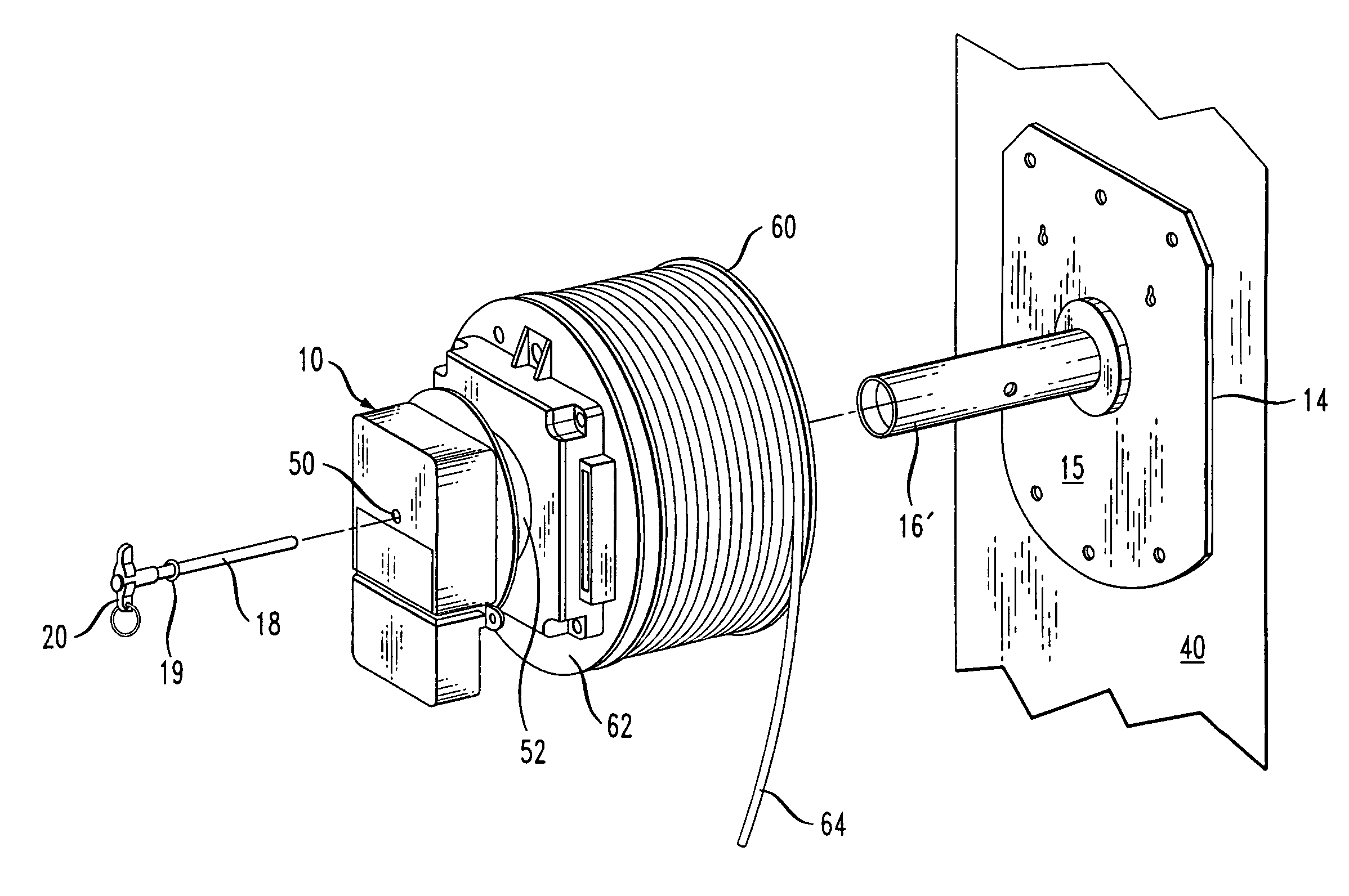
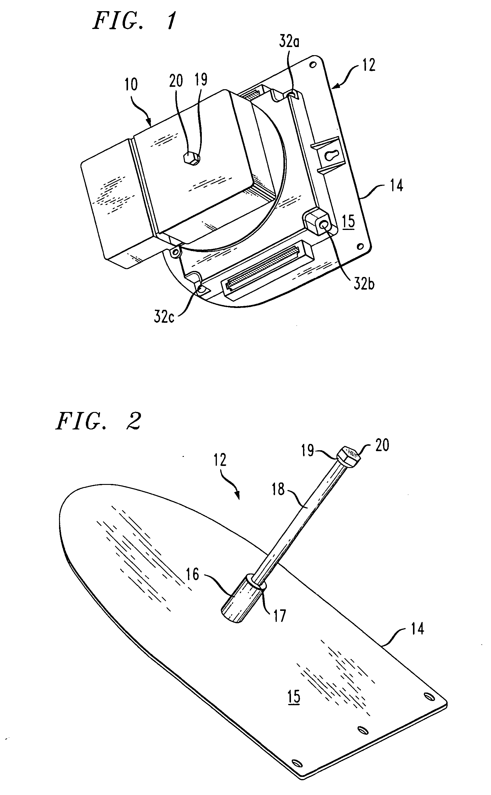
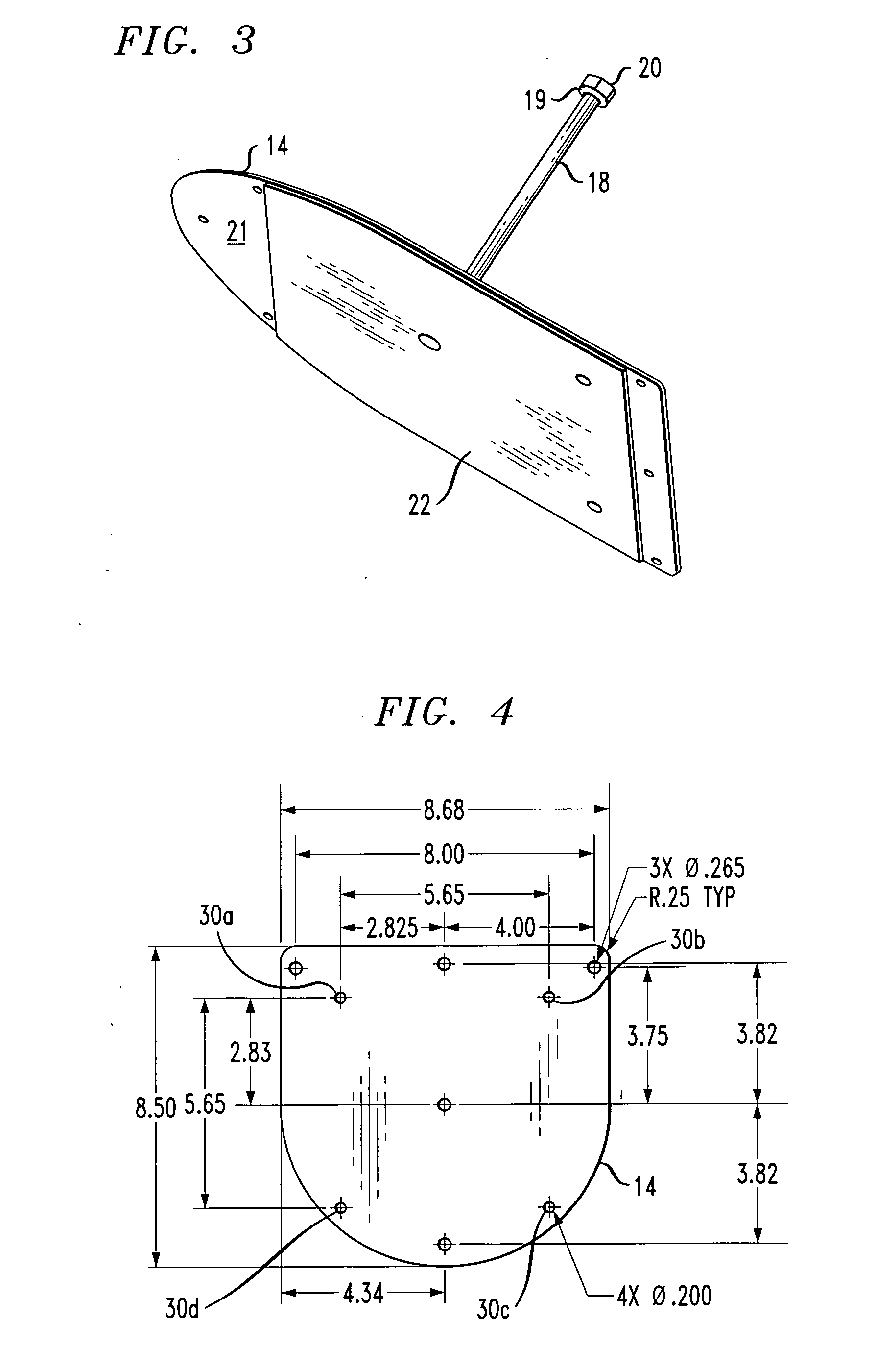
[0021]FIG. 1 shows a fiber optic cable drop box 10 such as, for example, the box of the mentioned '169 and '785 applications, wherein the box 10 is operatively supported on a spooling tool 12 according to the invention. FIG. 2 shows a base plate 14 of the tool 12, and an elongate arbor 18 dimensioned and formed to be inserted into an axial through passage that opens atop the drop box 10 in FIG. 1. Typical dimensions for one embodiment of the base plate 14 are given in inches in FIG. 4.

[0022]The base plate 14 may be generally “D” or rectangularly shaped and formed, for example, from zinc plated 16 gauge cold rolled steel (0.060 inch thick), aluminum, or equivalent rigid and durable sheet material. As shown in FIG. 2, a stud or post 16 has a bottom end that is fixed at a central location on an upper major surface 15 of the base plate 14. In the illustrated embodiment, the stud 16 has an axial bore that opens at a top end 17 of the stud. If the tool 12 is to be used with the drop box 1...


PUM


Abstract

A spooling tool for paying out a fiber optic cable prewound on a spool region of a drop box or on an associated spool, when installing a cable at a user's premises. In one embodiment, the tool includes a base plate and a stud projecting from one side of the plate. An elongate arbor has one end secured to the stud in such a manner as to support the arbor perpendicular to the base plate. The arbor is dimensioned to pass through an axial passage in the box so that the box pivots on the arbor when the cable is unwound by an installer. A cap mechanism at the opposite end of the arbor retains the drop box on the arbor, and applies enough drag on the box to inhibit it from free wheeling on the arbor.

Description

CROSS REFERENCE TO RELATED APPLICATION[0001]This application claims priority under 35 U.S.C. § 119(e) of co-pending U.S. Provisional Patent Application No. 60 / 945,611 filed Jun. 22, 2007, and entitled “Fiber Optic Rapid Spooling Tool”.BACKGROUND OF THE INVENTION[0002]1. Field of the Invention[0003]The present invention concerns a tool that facilitates paying out a cable from a spool or drum while the cable is installed at a user's premises.[0004]2. Discussion of the Known Art[0005]Installations of fiber optic cabling at a user's premises typically required winding a predetermined length of cable on a reel, and then pulling a free end of the cable off of the reel and down a riser shaft. The free end of the cable is then terminated in a building entrance box for connection with an outside cable from a service provider. It will be understood that such a procedure normally requires at least two technicians or installers, that is, one person to hold the reel as the cable is unwound, and ...

Claims


Application Information

Patent Timeline
IPC IPC(8): B65H16/04
CPCB65H49/327B65H2701/32G02B6/4457G02B6/4466G02B6/475
Inventor HENDRICKSON, DANIELZHANG, HONGBONAHAR, RATHINDRA
Owner COMMSCOPE TECH LLC
Why Eureka
Try Eureka