
Measuring Cerebral Oxygen Saturation

a technology of oxygen saturation and cerebral oxygen, applied in the field of medical devices, can solve the problems of inability inability to interact with substances in a medium, and difficulty of current near-infrared devices to detect various properties of deep layer tissu

Active Publication Date: 2008-12-25
VIOPTIX
View PDF40 Cites 59 Cited by
  • Summary
  • Abstract
  • Description
  • Claims
  • Application Information

AI Technical Summary

Benefits of technology

[0020]A near distance from the set of sources to the first set of detectors may b

Problems solved by technology

Many substances in a medium may interact or interfere with the near-infrared light waves propagating therethrough.
For example, current near-infrared devices have difficulty detecting various properties of deep layer tissue, such as the brain.

Method used


Image

  • Measuring Cerebral Oxygen Saturation
  • Measuring Cerebral Oxygen Saturation
  • Measuring Cerebral Oxygen Saturation

Examples


Embodiment Construction

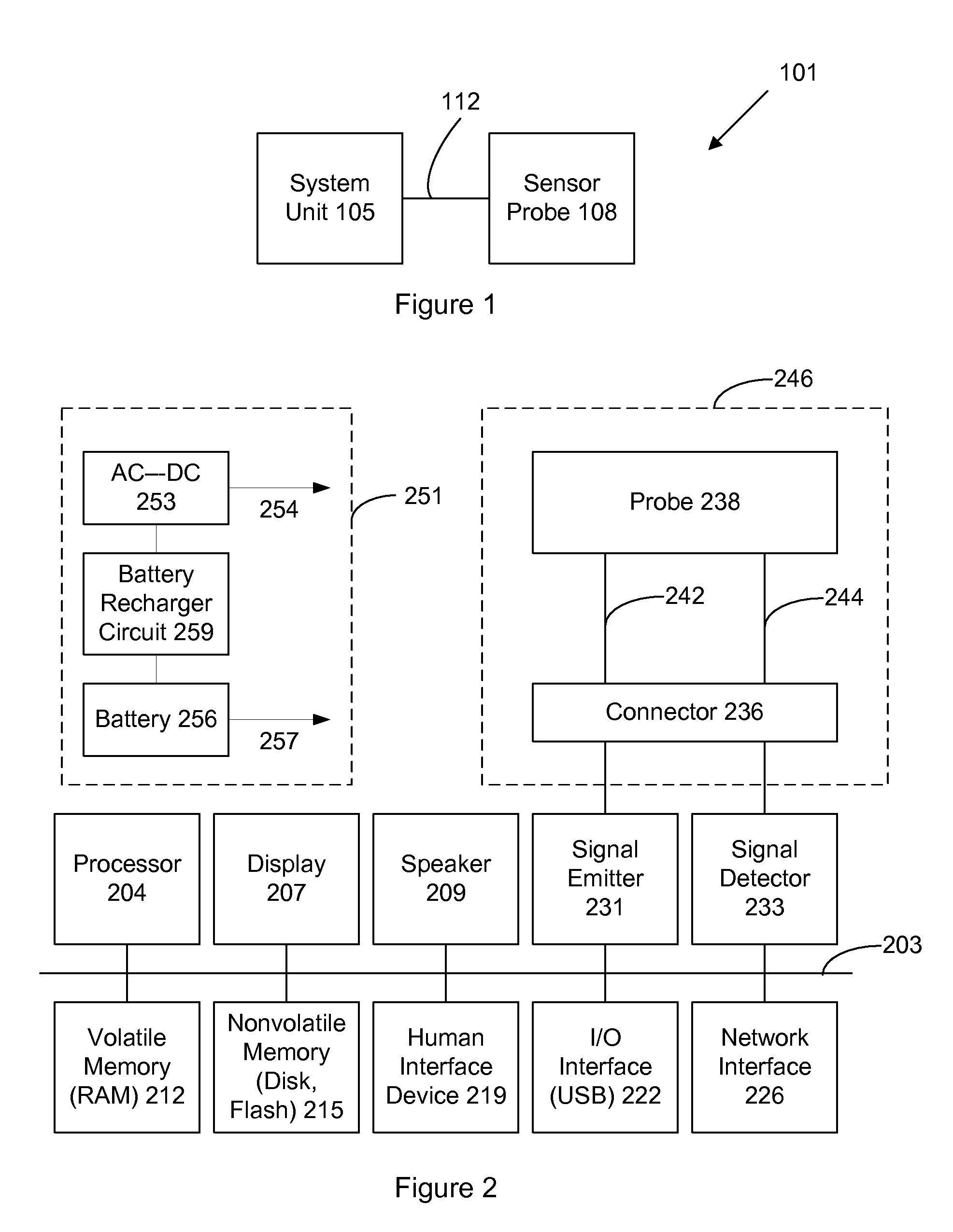
[0040]FIG. 1 shows an oximeter system 101 for measuring oxygen saturation of blood in a patient. The system includes a system unit 105 and a sensor probe 108, which is connected to the system unit via a wired connection 112. Connection 112 may be an electrical, optical, or another wired connection including any number of wires (e.g., one, two, three, four, five, six, or more wires or optical fibers). In other implementations of the invention, however, connection 112 may be wireless such as via a radio frequency (RF) or infrared communication.

[0041]Typically, the system is used by placing the sensor probe in contact or close proximity to tissue (e.g., skin) at a site where an oxygen saturation or other related measurement is desired. The system unit causes an input signal to be emitted by the sensor probe into the tissue (e.g., human tissue). There may be multiple input signals, and these signals may have varying or different wavelengths. The input signal is transmitted into or throu...


PUM


Abstract

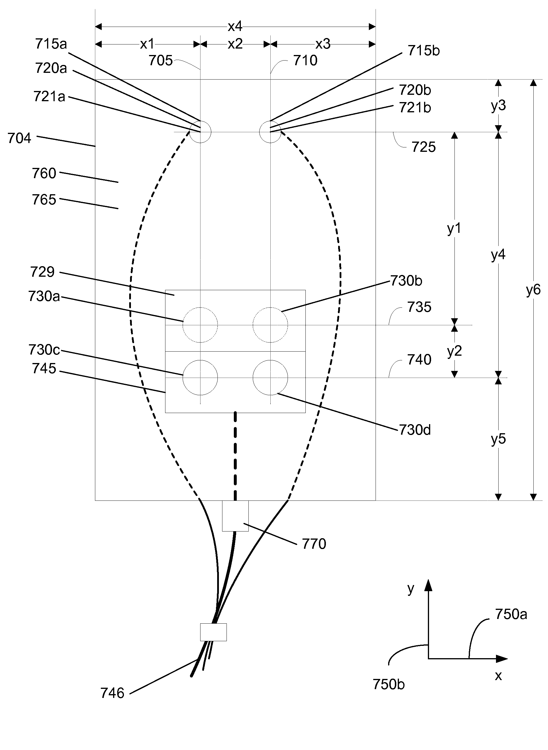
A device includes source and detector sensors. In a specific implementation, the device has two near detectors, two far detectors, and two sources. The two near detectors are arranged closer to the two sources than the two far detectors. A light-diffusing layer covers the two near detectors. The device may be part of a medical device that is used to monitor or measure oxygen saturation levels in a tissue. In a specific implementation, light is transmitted into the tissue and received by the detectors. An attenuation coefficient is first calculated for a shallow layer of tissue. The attenuation coefficient is then used to calculate an attenuation coefficient for a deep layer of tissue.

Description

CROSS-REFERENCE TO RELATED APPLICATIONS[0001]This patent application is a continuation-in-part of U.S. design patent applications 29 / 281,301, filed Jun. 20, 2007, issued as U.S. design patent D568,479 on May 6, 2008, and 29 / 305,102, filed Mar. 13, 2008, which are incorporated by reference along with all other references cited in this application.BACKGROUND OF THE INVENTION[0002]The present invention relates to medical devices and their manufacture. More particularly, the present invention relates to patient monitoring devices and methods.[0003]Patient monitoring systems measure, display, and sometimes store physiological data. Patient monitoring systems are now used in a wide variety of applications. This includes, for example, hospital, ambulatory, and home health care. Hospitals routinely measure and analyze the vital signs of surgical, trauma, and other patients from admission through discharge. There are many different types of monitoring devices. For example, there are monitori...

Claims


Application Information

Patent Timeline
IPC IPC(8): G01N21/00
CPCA61B5/14552A61B5/14553A61B2562/0238A61B2562/0242A61B2562/043
Inventor MAO, JIMMY JIAN-MINLASH, ROBERT E.
Owner VIOPTIX
Learn More