Combinational PZT And MEMS Beam Steering

a beam steering and pzt technology, applied in the field of piezoelectric light guides, can solve the problems of beam spreading and/or beam wandering, communication signals directed toward a receiver may be off target,

Active Publication Date: 2008-12-25
CUBIC CORPORATION
View PDF5 Cites 3 Cited by
  • Summary
  • Abstract
  • Description
  • Claims
  • Application Information

AI Technical Summary

Benefits of technology

[0007]Another beam steering system is also provided according to another embodiment. The beam steering system may include a laser that provides a beam of laser light, a piezoelectric tube, a scanning microelectromechanical mirror, and a controller. The piezoelectric tube may be cylindrically shaped. The light guide may be housed within the piezoelectric tube and at least four piezoelectric elements may be coupled radially around the piezoelectric tube. The piezoelectric tube may be coupled with the laser such that at least a portion of a beam of laser light from the laser may be conducted through the light guide. The scanning microelectromechanical mirror may include a steering device coupled with the piezoelectric tube. The beam of light may be incident on the scanning microelectromechanical mirror after exiting t

Problems solved by technology

Atmospheric conditions often cause beam spreading and/or beam wander in a light beam.
Due to

Method used


Image

  • Combinational PZT And MEMS Beam Steering
  • Combinational PZT And MEMS Beam Steering
  • Combinational PZT And MEMS Beam Steering

Examples


Embodiment Construction

[0017]The ensuing description provides preferred exemplary embodiment(s) only, and is not intended to limit the scope, applicability or configuration of the disclosure. Rather, the ensuing description of the preferred exemplary embodiment(s) will provide those skilled in the art with an enabling description for implementing a preferred exemplary embodiment. It should be understood that various changes may be made in the function and arrangement of elements without departing from the spirit and scope as set forth in the appended claims.

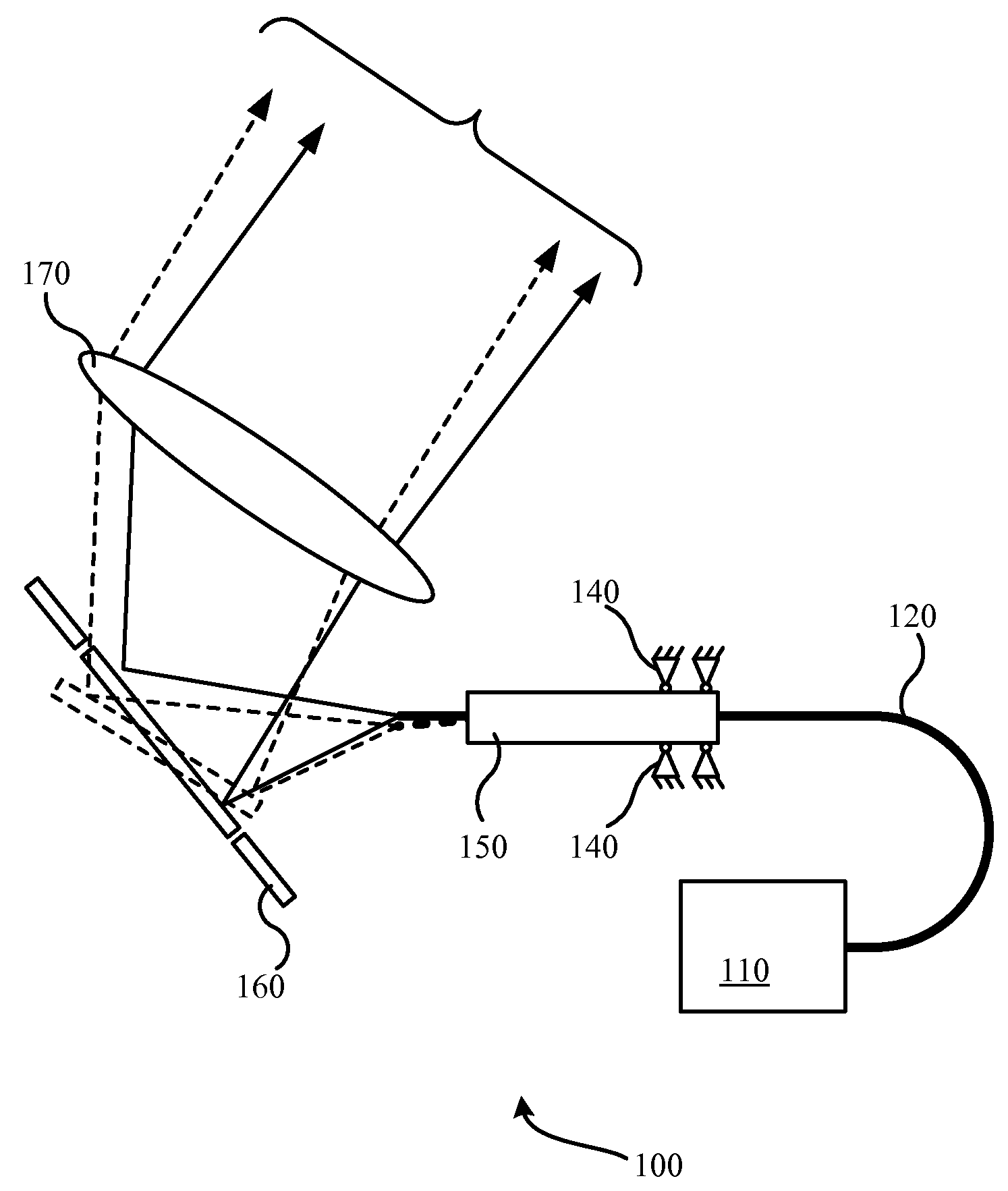
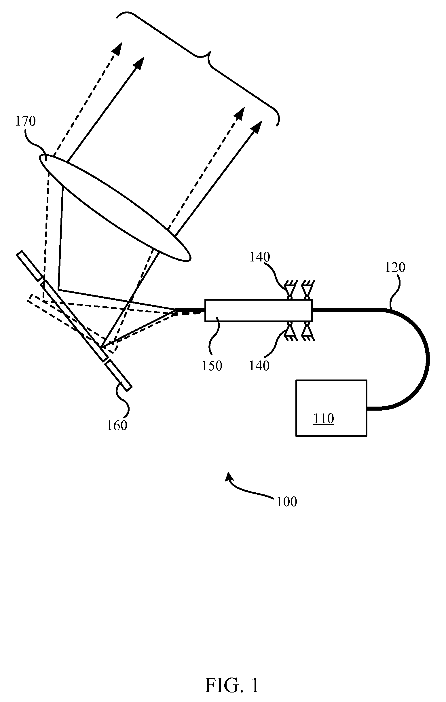
[0018]Various embodiments of the invention provide for a decoupled beam dithering and beam steering device. That is, the dithering mechanism and the beam steering mechanisms are separated and can be independently controlled. This decoupling may allow for high frequency dithering with lower frequency steering, and / or provide low beam deviation dithering with higher beam deviation steering. A piezoelectric light guide may be used as the dithering mechani...


PUM


Abstract

Beam steering systems and methods are disclosed according to various embodiments. A beam steering system may include a laser that produces a beam of light. The beam of light may then be directed through a piezoelectric tube that includes a light guide and one or more piezoelectric elements. The piezoelectric tube is coupled with the light source, such that the beam of light is conducted through the light guide. The piezoelectric tube is coupled with a scanning optical element that includes an optical element and a steering device. A controller may be communicatively coupled with the light source, the piezoelectric tube and the scanning optical element. The controller may include instructions to dither the beam of light with the piezoelectric tube and/or instructions to steer the beam of light with the scanning optical element.

Description

CROSS-REFERENCES TO RELATED APPLICATIONS[0001]This application is a non-provisional, and claims the benefit, of commonly assigned U.S. Provisional Patent Application No. 60 / 945,302, filed Jun. 20, 2007, entitled “Combinational PZT And MEMS Beam Steering,” the entirety of which is herein incorporated by reference for all purposes.BACKGROUND[0002]This disclosure relates in general to piezoelectric light guides and, but not by way of limitation, to piezoelectric light guides as a dithering tool in a beam steering application among other things.[0003]Atmospheric conditions often cause beam spreading and / or beam wander in a light beam. In some applications, light beams are used to communicate between a transmitter and a receiver. Due to such atmospheric affects, communication signals directed toward a receiver may be off target. Moreover, because these atmospheric affects are often transient, transmitters often employ beam steering and / or beam dithering protocols to track a receiver and / ...

Claims


Application Information

Patent Timeline
IPC IPC(8): G02F1/295
CPCG02B26/101G02B27/0031
Inventor MARYFIELD, TONYDADKHAH, MAHYAR
Owner CUBIC CORPORATION
Why Eureka
Try Eureka