Noise control device

a noise control and noise technology, applied in the field of noise control devices, can solve the problems of large amount of calculation, inability to obtain noise reduction effect, difficult to predict a change in noise in advance, etc., and achieve the effect of reducing an unspecified number of noises arriving

Active Publication Date: 2008-12-25
PANASONIC CORP
View PDF5 Cites 39 Cited by
  • Summary
  • Abstract
  • Description
  • Claims
  • Application Information

AI Technical Summary

Benefits of technology

[0024]Therefore, an object of the present invention is, in view of the above problem, to provide a n

Problems solved by technology

When, e.g., an engine sound, which is a noise whose characteristic constantly changes, is to be controlled, predicting a change in the noise in advance is difficult even if a position of a source of the noise can be specified.
In other words, a noise red

Method used


Image

  • Noise control device
  • Noise control device
  • Noise control device

Examples


first embodiment

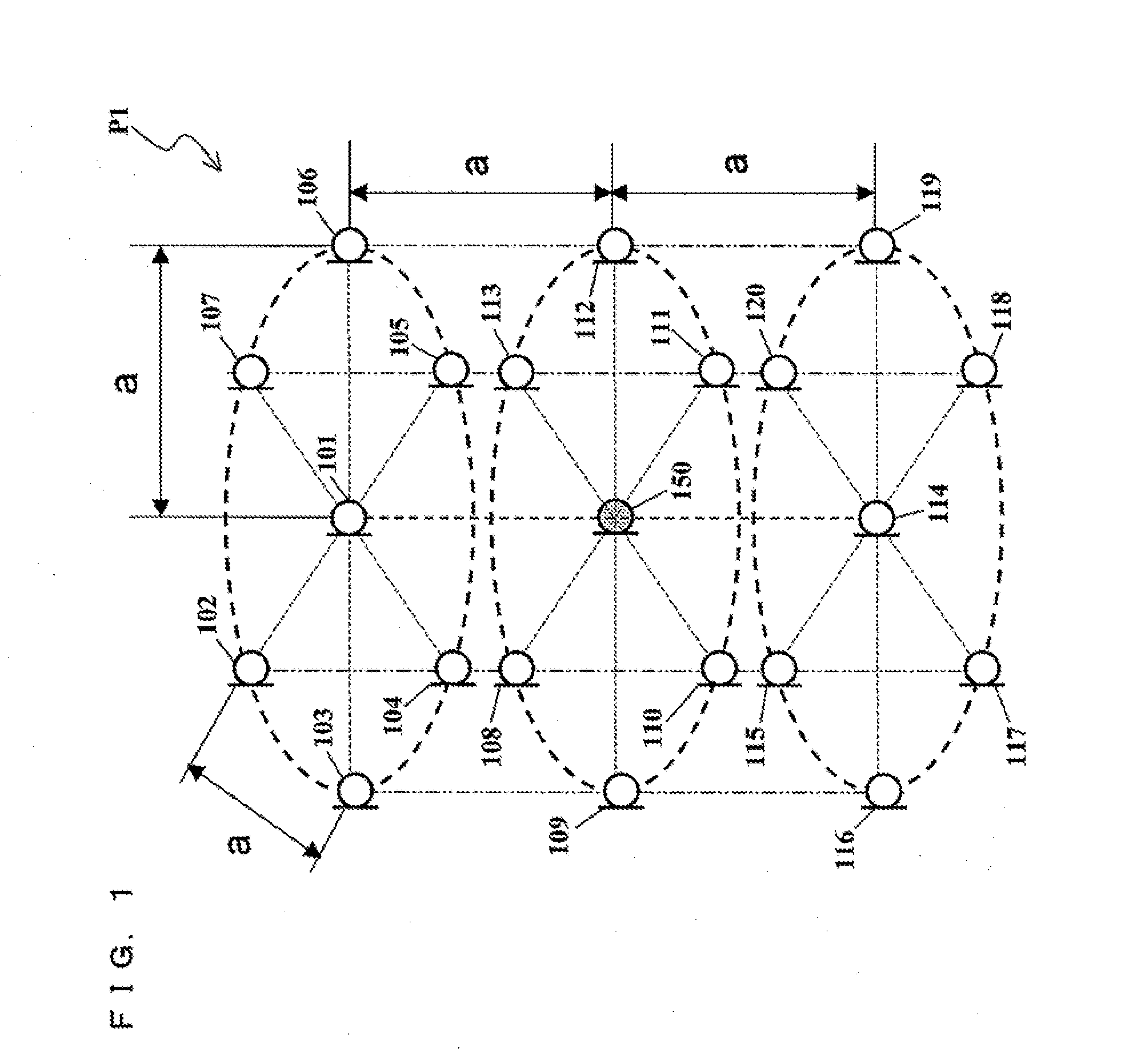
[0084]Described below with reference to FIGS. 7 and 8 is a structure of a noise control device according to a first embodiment of the present invention. FIG. 7 shows a circuit structure of the noise control device according to the first embodiment. FIG. 8 shows that noise microphones are placed in the placement pattern P1. It is assumed in FIG. 8 that an unspecified number of noises N are present outside a space which is formed by the noise microphones and which has an approximately circular cylindrical shape.

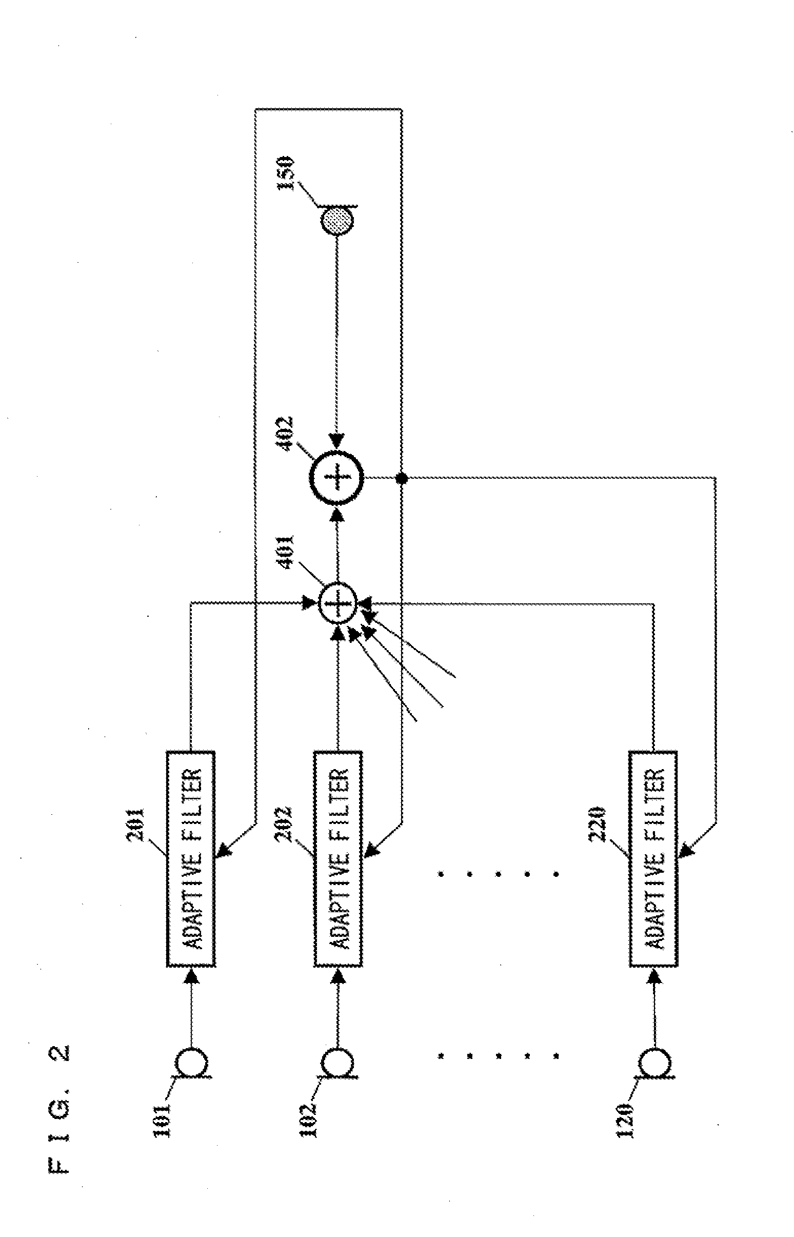
[0085]In FIG. 7, the noise control device is structured with noise microphones 10-1 to 10-n, adaptive filters 20-1 to 20-n, an adder 30, a control speaker 40 and an error microphone 50. Here, n is an integer no less than 1. Also in FIG. 8, n=20.

[0086]The noise microphones 10-1 to 10-n are noise detectors each for detecting a plurality of noises. The noise microphones each detect the plurality of noises arriving thereat, and output the detected noises as a noise signal. The nois...

second embodiment

[0097]In the first embodiment, the noise microphones are placed in the placement pattern P1 shown in FIG. 1. Described below in the present embodiment is an exemplary placement pattern of the noise microphones, which is different from the placement pattern P1 and which allows an unspecified number of noises to be reduced.

[0098](Placement Pattern P2)

[0099]Hereinafter, a placement pattern P2 will be described with reference to FIGS. 12A and 12B. FIG. 12A shows a top view of the placement pattern P2, and FIG. 12B is a side view of the placement pattern P2. In the placement pattern P2, the noise microphones 10-1 to 10-20 are placed so as to surround the control speaker 40 and the error microphone 50, and so as to form a polyhedral-shaped space having an approximately spherical shape, which polyhedral-shaped space has the error microphone 50 at the center thereof. In other words, also in the placement pattern P2, the control speaker 40 and the error microphone 50 are placed within the po...

third embodiment

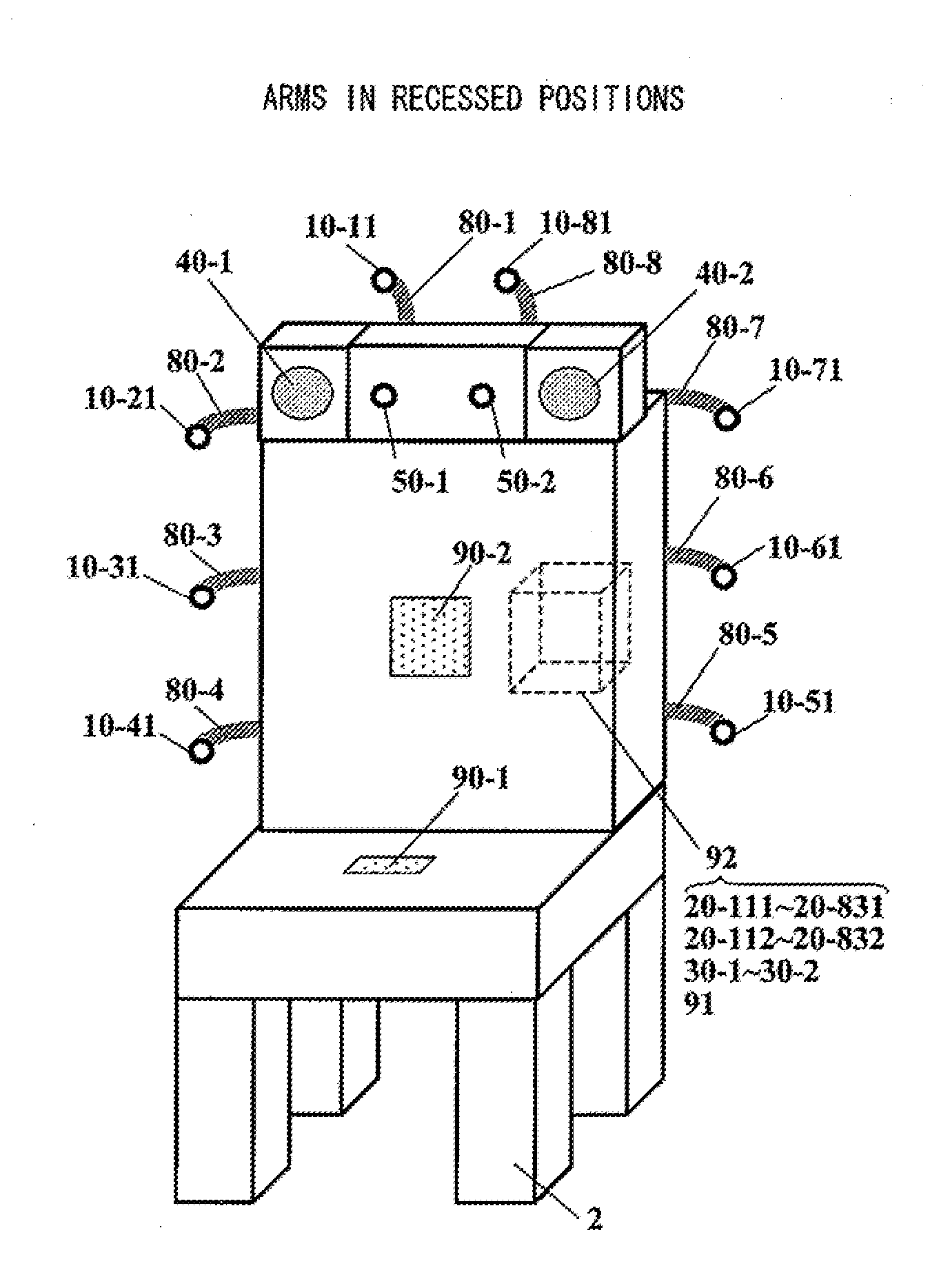
[0109]Hereinafter, a structure of the noise control device according to a third embodiment of the present invention will be described with reference to FIGS. 14 and 15. FIG. 14 shows a circuit structure of the noise control device according to the third embodiment. FIG. 15A shows a top view of the placement pattern P2, and FIG. 15B shows a side view of the placement pattern P2.

[0110]In FIG. 14, the noise control device comprises the noise microphones 10-1 to 10-n, adaptive filters 20-11 to 20-n1, adaptive filters 20-12 to 20-n2, adders 30-1 and 30-2, control speakers 40-1 and 40-2, and error microphones 50-1 and 50-2. Note that, n is an integer no less than 1. In FIGS. 15A and 15B, n=20.

[0111]The noise control device according to the present embodiment has a different circuit structure from that of FIG. 7 in that the noise control device according to the present embodiment has two adaptive filters for each noise microphone, and has two adders, two control speakers and two error micr...


PUM


Abstract

A noise control device according to the present invention comprises: four or more noise detectors each for detecting a plurality of noises arriving thereat, and outputting the noises as a noise signal; a control speaker for radiating, to a control point, a control sound based on each noise signal; and a filter section for signal-processing noise signals from the noise detectors by using filter coefficients which respectively correspond to the four or more noise detectors and which are set such that the control sound from the control speaker reduces the plurality of noises arriving at the control point, and for adding up all the signal-processed noise signals, and for outputting a resultant signal to the control speaker. The control point and the control speaker are provided within a polyhedral-shaped space whose apexes are placement positions of the noise detectors.

Description

BACKGROUND OF THE INVENTION[0001]1. Field of the Invention[0002]The present invention relates to a noise control device, and particularly relates to a noise control device for actively reducing an unspecified number of noises arriving at a control point in a three-dimensional space.[0003]2. Description of the Background Art[0004]From a long time ago, there is a concept of so-called active noise control for reproducing, from a control speaker, a sound which is in an antiphase to a noise, thereby negating the noise. First, active noise control based on analogue feedback control (hereinafter, referred to as a FB control) was put to practical use. Currently, this analogue FB control is commonly used in a headphone or the like. In recent years, with the development in digital devices such as DSP and in digital signal processing technology, active noise control based on feedforward control (hereinafter, referred to as FF control) using adaptive filters, is in practical use for air-conditi...

Claims


Application Information

Patent Timeline
IPC IPC(8): G10K11/16
CPCG10K2210/12G10K2210/1281G10K11/178G10K2210/1283G10K2210/3214G10K2210/1282G10K11/17857G10K11/17881
Inventor KANO, HIROYUKI
Owner PANASONIC CORP
Why Eureka
Try Eureka