Apparatus and Method for Detecting Diastolic Heart Failure

a technology medical equipment, which is applied in the field of implantable medical equipment and a detection method of diastolic heart failure, dhf, and a pacemaker, can solve the problem of difficult to separate diastolic and systolic heart failur

Inactive Publication Date: 2008-12-25
ST JUDE MEDICAL
View PDF5 Cites 2 Cited by
  • Summary
  • Abstract
  • Description
  • Claims
  • Application Information

AI Technical Summary

Problems solved by technology

In addition it has been hard to separate diastolic and syst

Method used


Image

  • Apparatus and Method for Detecting Diastolic Heart Failure
  • Apparatus and Method for Detecting Diastolic Heart Failure
  • Apparatus and Method for Detecting Diastolic Heart Failure

Examples


Embodiment Construction

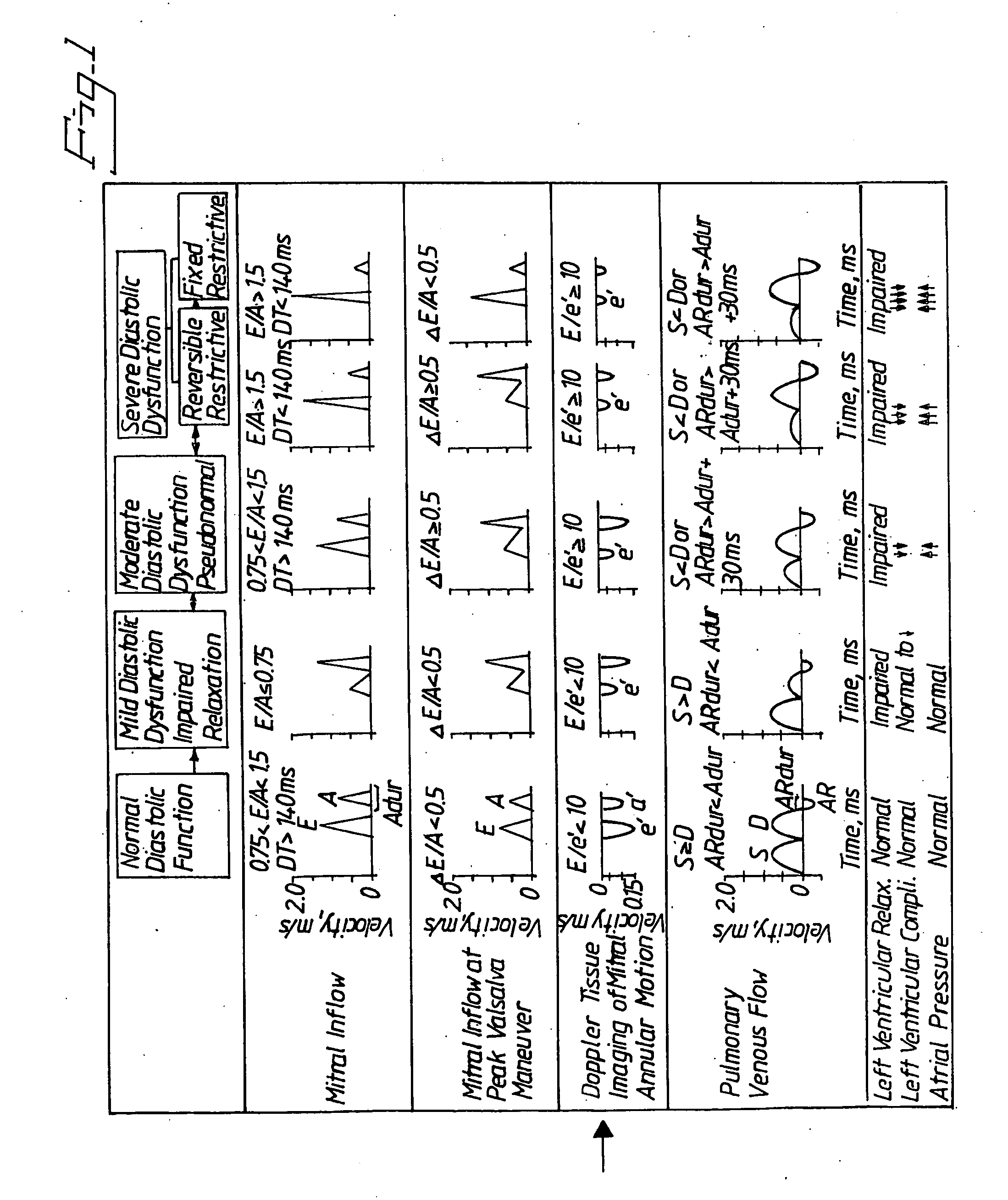
[0025]In the diagrams for Doppler Tissue Imaging of Mitral Annular Motion of FIG. 1, the curve e′ shows the velocity of mitral annulus motion during early diastole. It is clear from the diagrams that the velocity of the mitral annulus motion decreases when the diastolic dysfunction gets more severe.

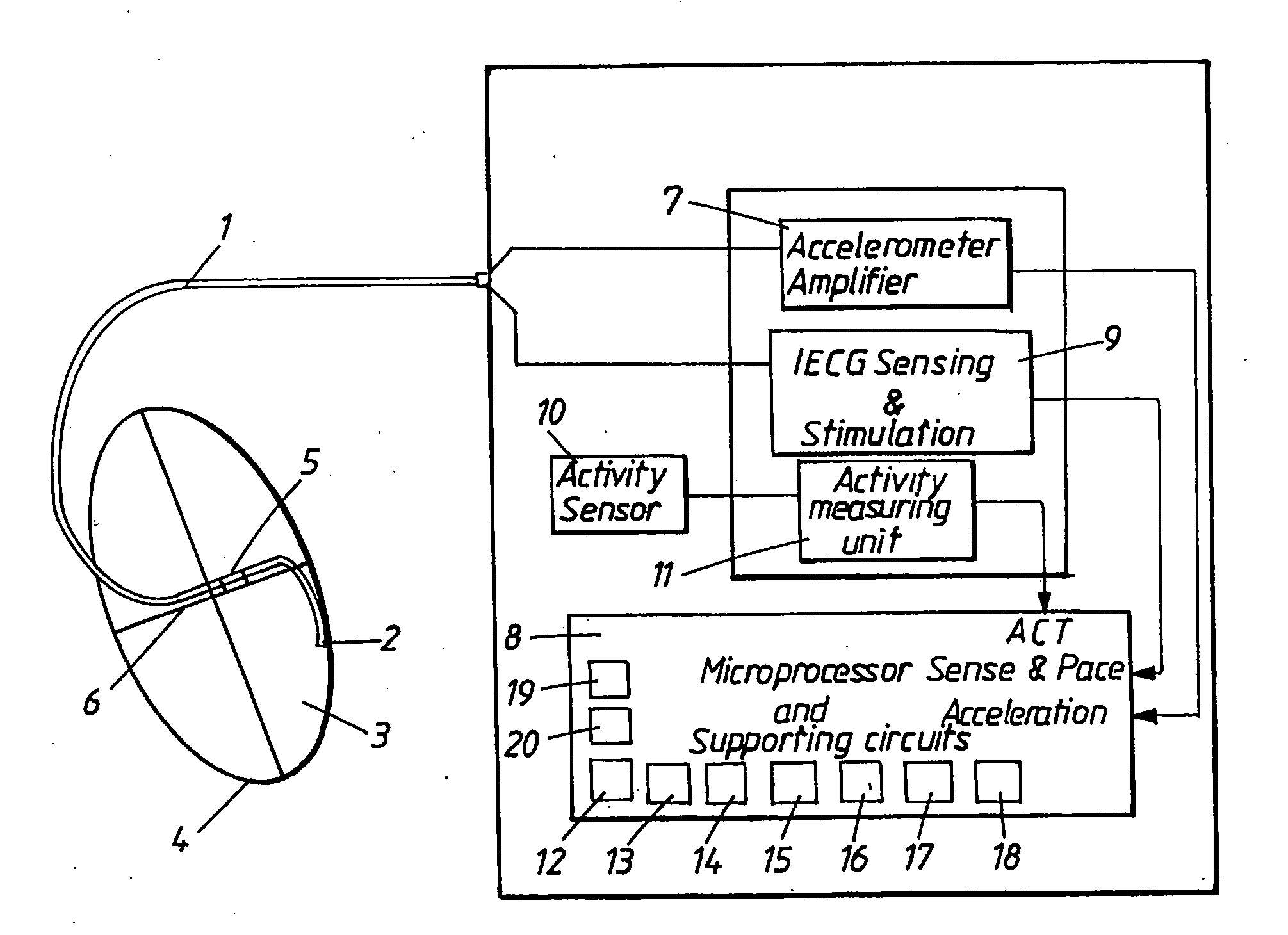
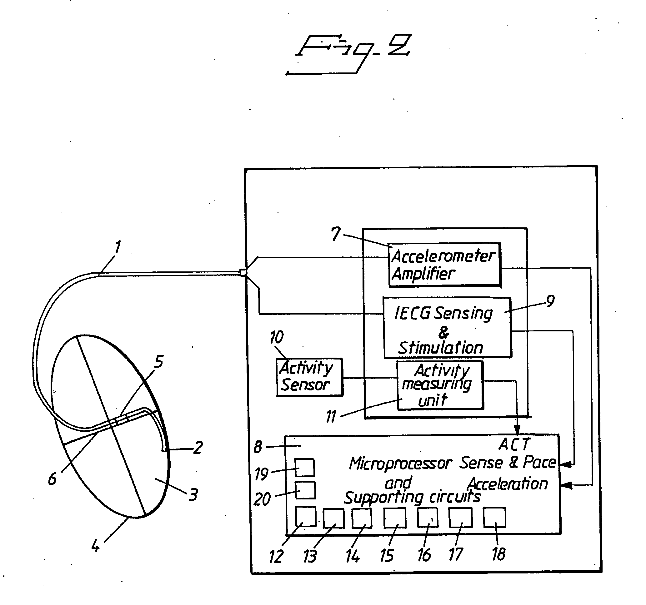
[0026]FIG. 2 shows an embodiment of a pacemaker comprising an apparatus according to the present invention. The pacemaker is adapted for left ventricular pacing only, and a left ventricular lead 1 of the pacemaker is with its electrode 2 connected to the left ventricle 3 of a patent's heart 4. Integrated with the lead 1 is an accelerometer 5 which is placed in the valve plane 6 of the patent's heart 4, but can also be placed close to the valve plane 6 in the lower part of the right atrium, or inside one of the ventricles. The accelerometer 5 is arranged to measure the acceleration of the valve plane 6 and is via the lead 1 connected to an accelerometer amplifier 7 arranged to amplify the ...


PUM


Abstract

In a method and implantable medical apparatus for detecting diastolic heart failure (DHF), and a pacemaker embodying such an apparatus, movement of the valve plane of the heart is measured and analyzed to identify a slowing of the movement of the valve plane as an indication of a DHF state of the heart. A signal indicative of this DHF state is emitted and, in the pacemaker, is used to control the administration of a pacing pulse therapy to the heart.

Description

TECHNICAL FIELD[0001]The present invention relates to an implantable medical apparatus and a method for detecting diastolic heart failure, DHF, and a pacemaker comprising said apparatus.BACKGROUND OF THE INVENTION[0002]There is a growing recognition that congestive heart failure caused by a predominant abnormality in the diastolic function, i.e. diastolic heart failure, DHF, is both common and causes significant morbidity and mortality. Therefore early detection of DHF is important. Patients do not, however, seem to have symptoms at an early stage. In addition it has been hard to separate diastolic and systolic heart failure, and they may also exist simultaneously.[0003]DHF is characterized by a slowing down of the recoil effect during early diastole, i.e. during the isovolumic ventricular relaxation and the rapid left ventricular filling phase, before the atrial contraction. This has been observed by measuring the velocity of the mitral annulus. According to an article by Margaret ...

Claims


Application Information

Patent Timeline
IPC IPC(8): A61N1/365A61B5/02
CPCA61B5/02405A61B5/0472A61B5/1107A61B5/686A61B2562/0219A61B5/6869A61B5/366
Inventor HEDBERG, SVEN-ERIK
Owner ST JUDE MEDICAL
Why Eureka
Try Eureka