Blood pump system for artificial heart and apparatus supervisory system

a blood pump and artificial heart technology, applied in the direction of heart stimulators, prostheses, therapy, etc., can solve the problems of inconvenient operation, inability to realize the duplexing of the alarm generating means according to (2) above, and inability to immediately inform the ear of the abnormal state of the alarm generating means,

Inactive Publication Date: 2008-12-25
TC1 LLC
View PDF7 Cites 49 Cited by
  • Summary
  • Abstract
  • Description
  • Claims
  • Application Information

AI Technical Summary

Benefits of technology

[0013]Thus, there is a need to realize duplexing of the system alarm with an inexpensive and small-sized configuration through the use of a reduced number of component parts and, further, to make it possible to provoke the user's or medical worker's attention upon a failure of the speaker, the alarm generating means or the like.
[0017]According to the embodiment of the present invention, duplexing of an alarm can be realized by use of an inexpensive and small-sized configuration. In addition, a configuration may be adopted in which an alarm signal is sent to an external monitor device by use of a radio signal upon a failure of the control unit (alarm generating means), whereby it is possible to arouse the user's or the like person's attention through utilizing the monitor device.

Problems solved by technology

Meanwhile, the alarm sound for confirmation used in (1) above is an audible sound and, therefore, is offensive to the ear if issued constantly.
Thus, the technology for realizing confirmation of the presence / absence of a failure by issuing an alarm sound for confirmation has had a drawback in that there is a time difference (time lag) from the time of failure to the time of confirmation and, hence, it is very difficult to immediately inform that the alarm generating means is in an abnormal state.
On the other hand, the duplexing of the alarm generating means according to (2) above cannot be realized inexpensively and in a small size.
In the case (A) where two systems of only the “speaker” are prepared in such a blood pump system for an artificial heart, a failure of the speaker driver 104 and its preceding stage results in that the alarm sound is not outputted, so that the effect of the duplexing cannot be obtained.

Method used


Image

  • Blood pump system for artificial heart and apparatus supervisory system
  • Blood pump system for artificial heart and apparatus supervisory system
  • Blood pump system for artificial heart and apparatus supervisory system

Examples


first embodiment

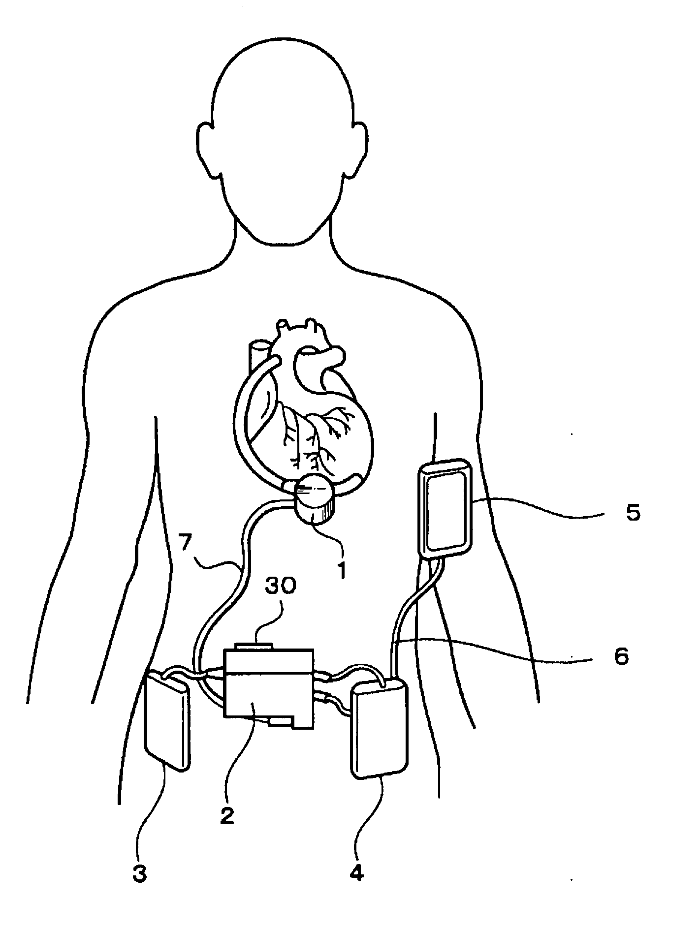
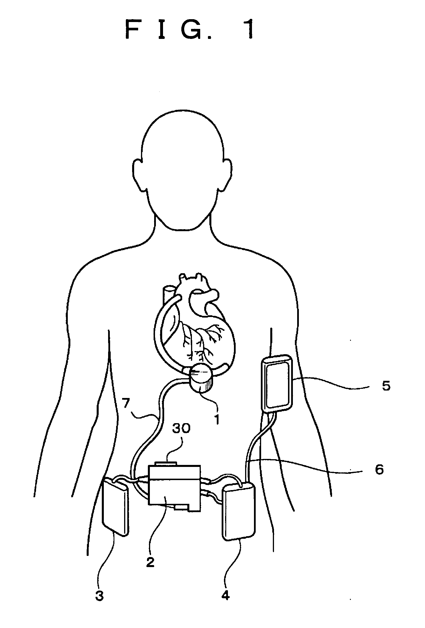
[0034]FIG. 3 is a block diagram of the blood pump system for an artificial heart according to a first embodiment. This embodiment corresponds to an example of the blood pump system for an artificial heart in which a detector 30 is mounted to a layout surface of a speaker 22 of a controller 2.

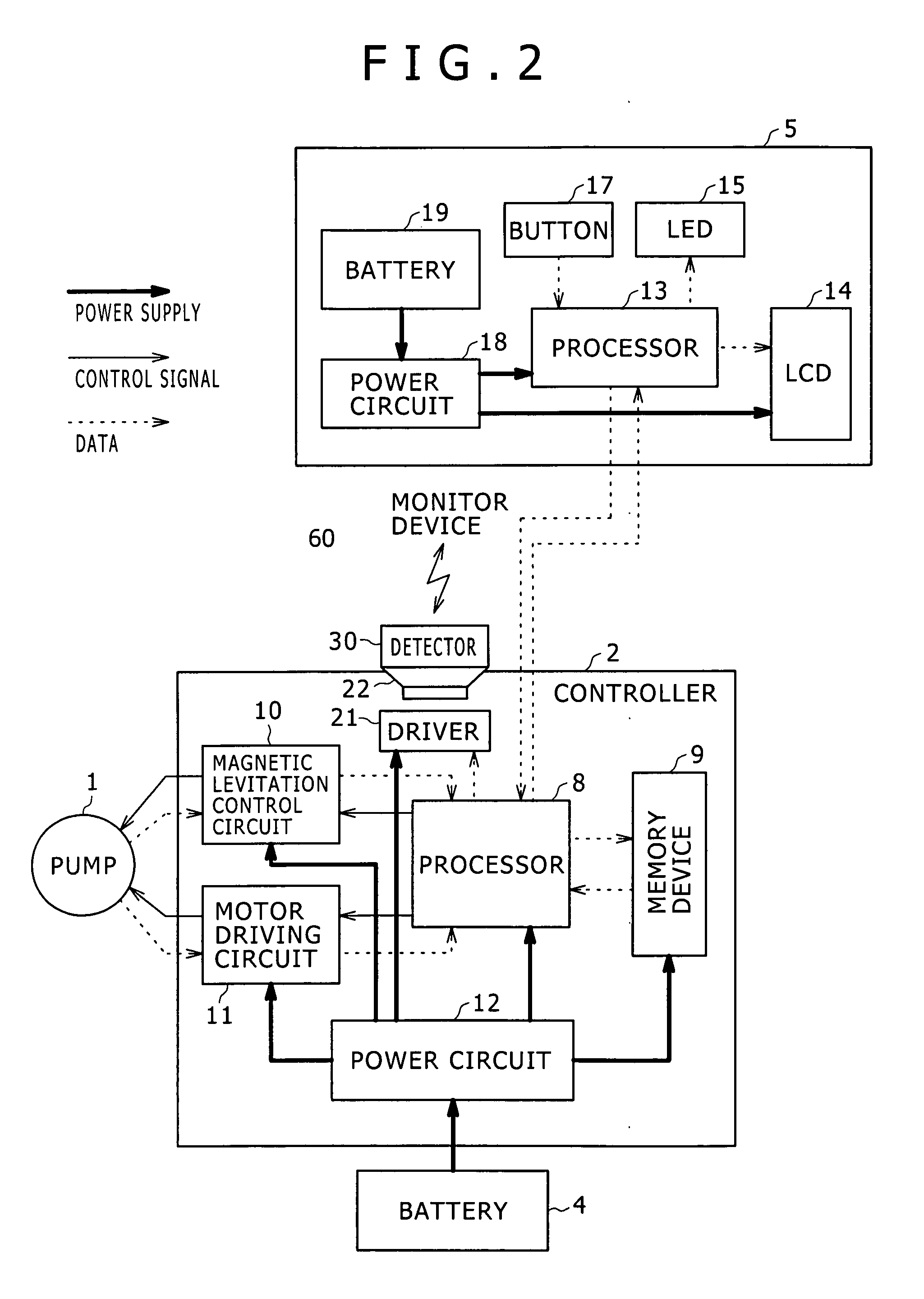
[0035]An alarm generating circuit 20 in the controller shown in FIG. 3 is a part (first alarm generating part) obtained by extracting and embodying the function as alarm generating means, which is one of the functions possessed by the processor 8 shown in FIG. 1. The alarm generating circuit 20 sends an alarm signal to the speaker 22 through a speaker driver 21 (omitted in the figure). Incidentally, in FIG. 3, the other parts of the controller 2 shown in FIG. 1 are omitted.

[0036]On the other hand, the detector 30 has an ultrasonic transducer 31, an ultrasonic signal detecting part 32, an oscillating circuit 33, a frequency modulating part 34, a high-frequency amplifying part 35 and an antenna 36...

second embodiment

[0060]FIG. 4 shows a block diagram of a blood pump system for an artificial heart according to a second embodiment. This embodiment corresponds to an example of the blood pump system for an artificial heart wherein a detector 50 is mounted to a predetermined heat radiating surface of a controller 2. Specifically, the second embodiment differs from the first embodiment (see FIG. 3) in that a temperature sensor is used in place of the ultrasonic transducer as the supervisory means of the detector, and that a temperature decision part is used in place of the ultrasonic signal detecting part as the determining means. In the following description, the parts in FIG. 4 corresponding to the parts in FIG. 3 above will be denoted by the same symbols as used above, and detailed description of the parts will be omitted.

[0061]As shown in FIG. 4, the detector 50 is so disposed that the temperature sensor 51 of the detector 50 is placed in contact with a heat radiating surface 2a of the controller...

third embodiment

[0079]FIG. 5 is a block diagram of a blood pump system for an artificial heart according to a third embodiment. This embodiment corresponds to an example wherein the detector in the blood pump system for an artificial heart in the first embodiment above is provided with an alarm generating function. Specifically, the third embodiment differs from the first embodiment (see FIG. 3) in that, instead of sending a radio signal containing alarm data from the detector to the monitor device, the detector is provided with a speaker driver 74 and a speaker 75 for the purpose of outputting an alarm. In the following description, the parts in FIG. 5 corresponding to the parts in FIG. 3 are denoted by the same symbols as used above, and detailed descriptions of these parts will be omitted.

[0080]The operation of a controller 2 is the same as in the first embodiment. Specifically, the controller 2 outputs an audible sound from a speaker 22 when a blood pump 1 is in an abnormal state needing genera...


PUM


Abstract

A blood pump system for an artificial heart including: a control unit for controlling a blood pump, the control unit including a first alarm generating part for generating a first alarm signal according to the state of the blood pump, and a speaker for outputting an audible sound upon receiving the first alarm signal when the blood pump is in an abnormal state; a supervisory section configured to supervise the state of the control unit; a determining section configured to determine whether the control unit is in an abnormal state or not, based on output signal from the supervisory section; and a second alarm generating part for generating a second alarm signal according to the state of the control unit, based on the result of determination by the determining section.

Description

BACKGROUND OF THE INVENTION[0001]The present invention relates to a technology of issuing an alarm according to the state of a controlled apparatus, particularly to an apparatus supervisory system suitable for application to a blood pump system for an artificial heart by which the state of the blood pump and the state of a controller for the blood pump are supervised and an alarm is issued as required.[0002]An artificial heart has hitherto been adopted as an apparatus capable of substituting for the function of a heart. An artificial heart is composed mainly of a blood pump for circulating the blood and a controller for controlling the operation of the blood pump. Upon an abnormal state generated in the operation of the blood pump, the controller functions as alarm generating means for generating an alarm to inform the user of the abnormal state.[0003]Since the blood pump of the artificial heart supports the human life directly, a failure of the alarm generating means may possibly b...

Claims


Application Information

Patent Timeline
Patent Type & Authority Applications(United States)
IPC IPC(8): A61M1/10A61M60/178A61M60/216A61M60/422A61M60/538A61M60/585A61M60/592A61M60/822A61M60/824A61M60/873
CPCA61M1/12A61M2205/17A61M2205/3507A61M2205/50A61M2205/502A61M1/122A61M1/101A61M1/1086A61M1/127A61M1/1013A61M60/148A61M60/216A61M60/592A61M60/585A61M60/824A61M60/422A61M60/178A61M60/538A61M60/873A61M60/822
Inventor YAEGASHI, MITSUTOSHI
Owner TC1 LLC
Why Eureka
Try Eureka