Combustion Control Apparatus and Method for Internal Combustion Engine

Inactive Publication Date: 2008-12-25
TOYOTA JIDOSHA KK +1
View PDF2 Cites 21 Cited by
  • Summary
  • Abstract
  • Description
  • Claims
  • Application Information

AI Technical Summary

Benefits of technology

[0017]This invention thus provides a control apparatus and control method that accurately distinguishes between true abnormal combustion in which combustion actually deteriorates and combustion that appears to be abnormal combustion but in which combustion does not actually deteriorate, such as normal combustion with retarded ignition.

Problems solved by technology

However, in actuality problems may arise if the combustion state in the cylinder is determined solely by the combustion barycentric position, as it is in JP-A-1-216073.
As a result, the pressure in the cylinder rises later, which may result in abnormal combustion in which less torque is generated.
In this case, the slower burning rate results in the combustion barycentric position becoming retarded.
For example, typically during abnormal combustion, ignition (the start of combustion) is retarded and the burning rate slows, and weak combustion continues until late into the combustion stroke.
Therefore, when the combustion state is determined solely by the combustion barycentric position, as it is with the apparatus described in JP-A-1-216073, it is not possible to distinguish between true abnormal combustion and normal combustion in which ignition is simply retarded as described above.
Therefore, normal combustion with retarded ignition may be erroneously determined as being abnormal combustion, and as a result, measures to improve combustion, such as advancing the spark timing or increasing the quantity of fuel injected, may be taken which may instead cause problems, e.g., they may adversely affect the quality of the exhaust gas.

Method used


Image

  • Combustion Control Apparatus and Method for Internal Combustion Engine
  • Combustion Control Apparatus and Method for Internal Combustion Engine
  • Combustion Control Apparatus and Method for Internal Combustion Engine

Examples


Embodiment Construction

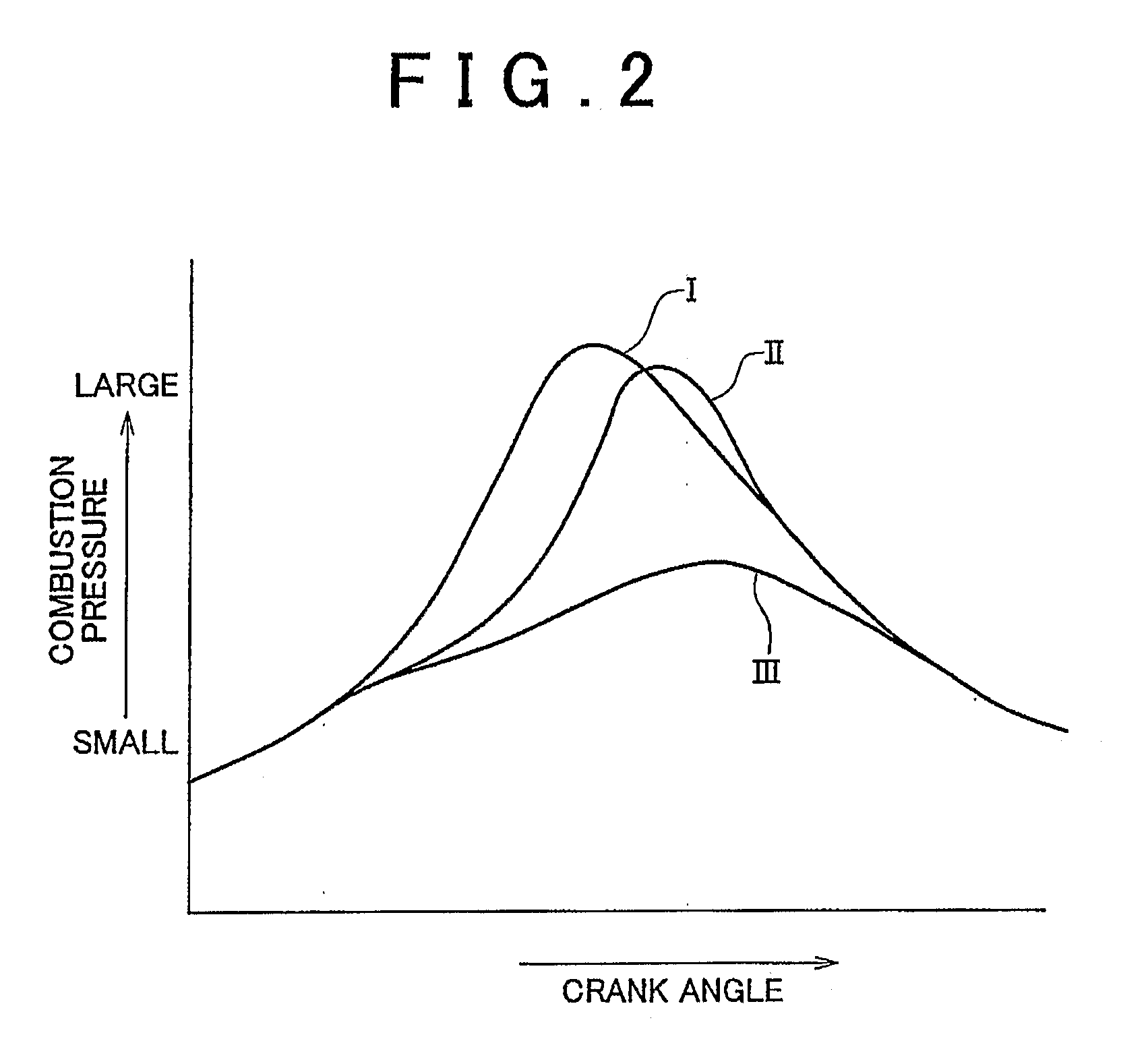
[0043]Hereinafter, an abnormal combustion determining principle of the invention will be described. FIG. 2 shows the change in the pressure in a cylinder during the combustion stroke according to the combustion state. The vertical axis in the drawing represents the combustion pressure and the horizontal axis represents the crank angle.

[0044]In FIG. 2, curve I shows the pressure change during normal combustion, curve III shows the pressure change during abnormal combustion, and curve II shows the pressure change during normal combustion with retarded ignition.

[0045]As shown in FIG. 2, with abnormal combustion (curve III), the pressure starts to rise (i.e., ignition) later than it does with normal combustion (curve I) and the rate at which the pressure increases (i.e., the burning rate) is also slower than it is with normal combustion. Because of this, the highest pressure in the cylinder is also much lower than it is with normal combustion, resulting in much less output torque from t...


PUM


Abstract

A control apparatus for an internal combustion engine includes cylinder internal pressure sensors provided in each cylinder of an engine, and calculates a heat generation quantity in each cylinder based on the detected cylinder internal pressure and a crank angle. The control apparatus then obtains a combustion barycentric position, which is the crank angle at which a predetermined ratio of heat, of the total heat generation quantity in a combustion cycle, is generated. The control apparatus also calculates, based on the heat generation quantity, an actual starting point of combustion, which is a crank angle at which combustion actually started in the cylinder, and obtains the crank angle of the relative combustion barycentric position with respect to the actual starting point of combustion. When this crank angle exceeds an upper limit value, it is determined that combustion has truly deteriorated.

Description

BACKGROUND OF THE INVENTION[0001]1. Field of the Invention[0002]The invention relates to a combustion control apparatus and combustion control method for an internal combustion engine. More particularly, the invention relates to a control apparatus and a control method for an internal combustion engine, which determines the combustion state of a cylinder based on the combustion pressure in the cylinder.[0003]2. Description of the Related Art[0004]A combustion control apparatus for an internal combustion engine is known which provides a cylinder internal pressure sensor that is capable of detecting the pressure inside a cylinder in each cylinder of an internal combustion engine. This combustion control apparatus calculates the amount of heat generated (hereinafter also referred to as the (“heat generation quantity”) in each cylinder based on the cylinder internal pressure (i.e., the combustion pressure) detected while the engine is operating, and controls the combustion state of each...

Claims


Application Information

Patent Timeline
IPC IPC(8): F02D45/00
CPCF02D35/023F02D35/028F02D2200/1015
Inventor MIYASHITA, SHIGEKIKOBAYASHI, MITSUYUKI
Owner TOYOTA JIDOSHA KK
Why Eureka
Try Eureka