Apparatus for the fibre-sorting or fibre-selection of a fibre bundle comprising textile fibres, especially for combing

Inactive Publication Date: 2009-01-01
TRUETZSCHLER GMBH & CO KG
View PDF55 Cites 37 Cited by
  • Summary
  • Abstract
  • Description
  • Claims
  • Application Information

AI Technical Summary

Benefits of technology

[0005]It is an aim of the invention to provide an apparatus of the kind described at the beginning which avoids or mitigates the mentioned disadvantages and whic

Problems solved by technology

High nip rates result in high acceleration.
The known flat combing machine has reached a performance limit with its nip rates, which prevents productivity from being increased.
Furthermore, the discontinuous mode of operation causes vibration in the entire machine, which generates dynamic alternating stresses.
Disadvantages of that combing machine are especially the large amount of equipment required and the low hourly production rate.
A particular problem is the discontinuous mode of operation of the combing heads.
Additional disadvantages result from large mass accelerations and reversing movements, with the result that high operating speeds are not possible.
Finally, the considerable amount of machine vibration results in irregularities in the depo

Method used


Image

  • Apparatus for the fibre-sorting or fibre-selection of a fibre bundle comprising textile fibres, especially for combing
  • Apparatus for the fibre-sorting or fibre-selection of a fibre bundle comprising textile fibres, especially for combing
  • Apparatus for the fibre-sorting or fibre-selection of a fibre bundle comprising textile fibres, especially for combing

Examples


Embodiment Construction

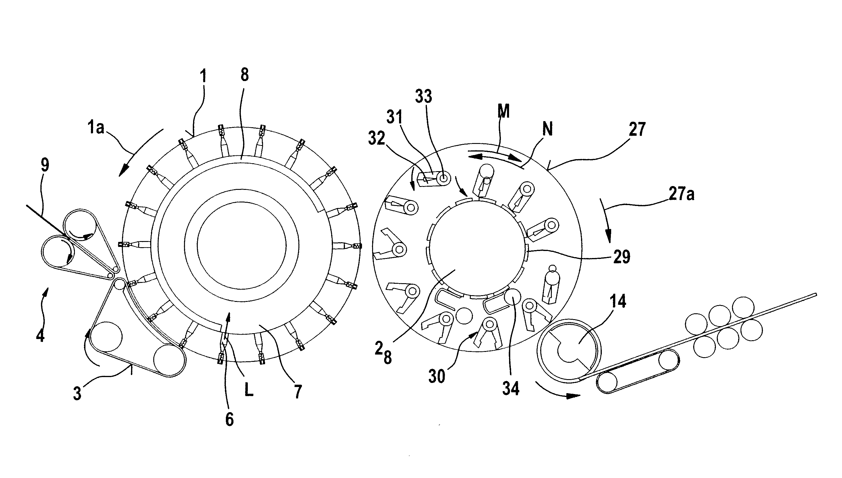
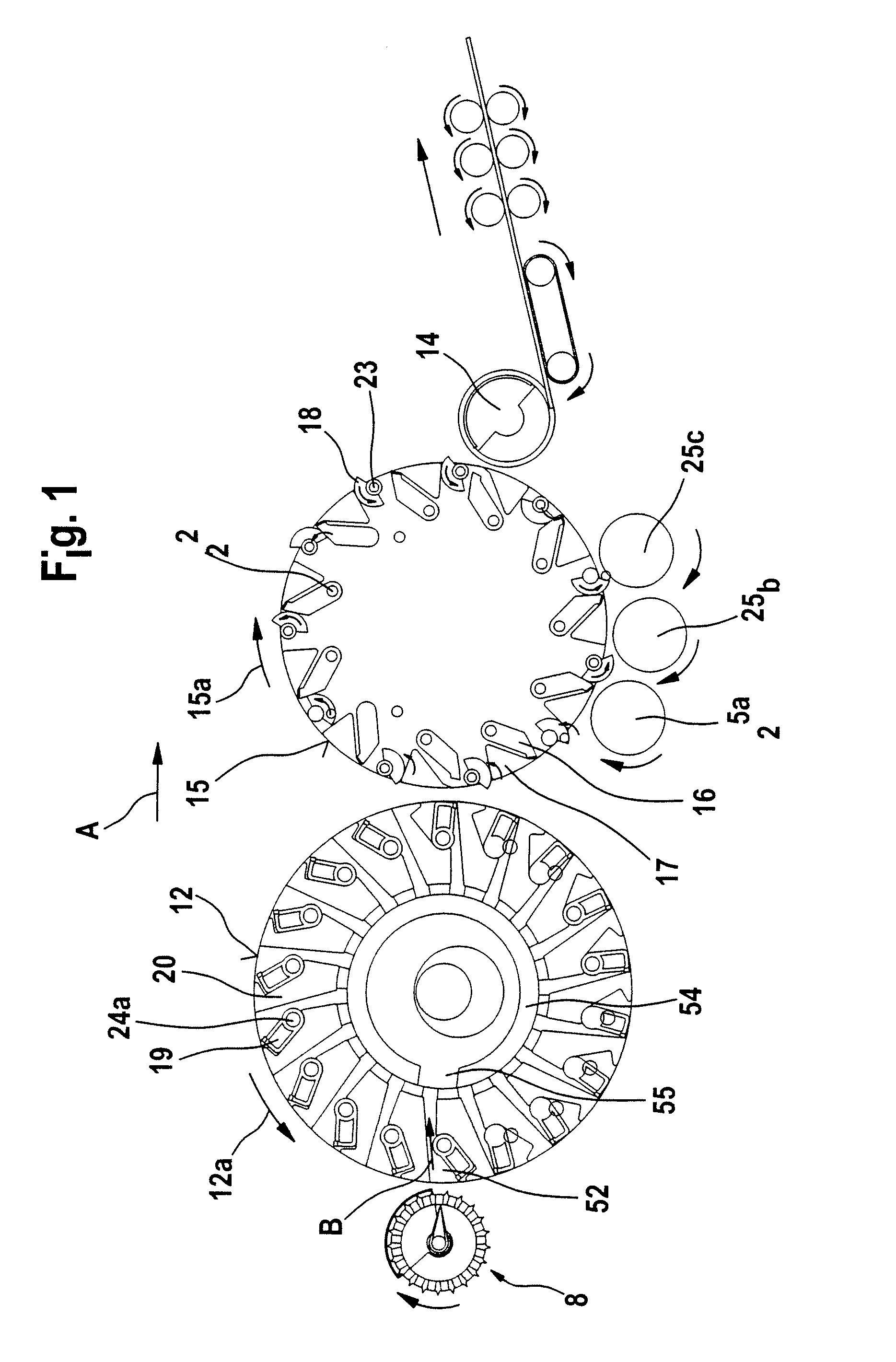
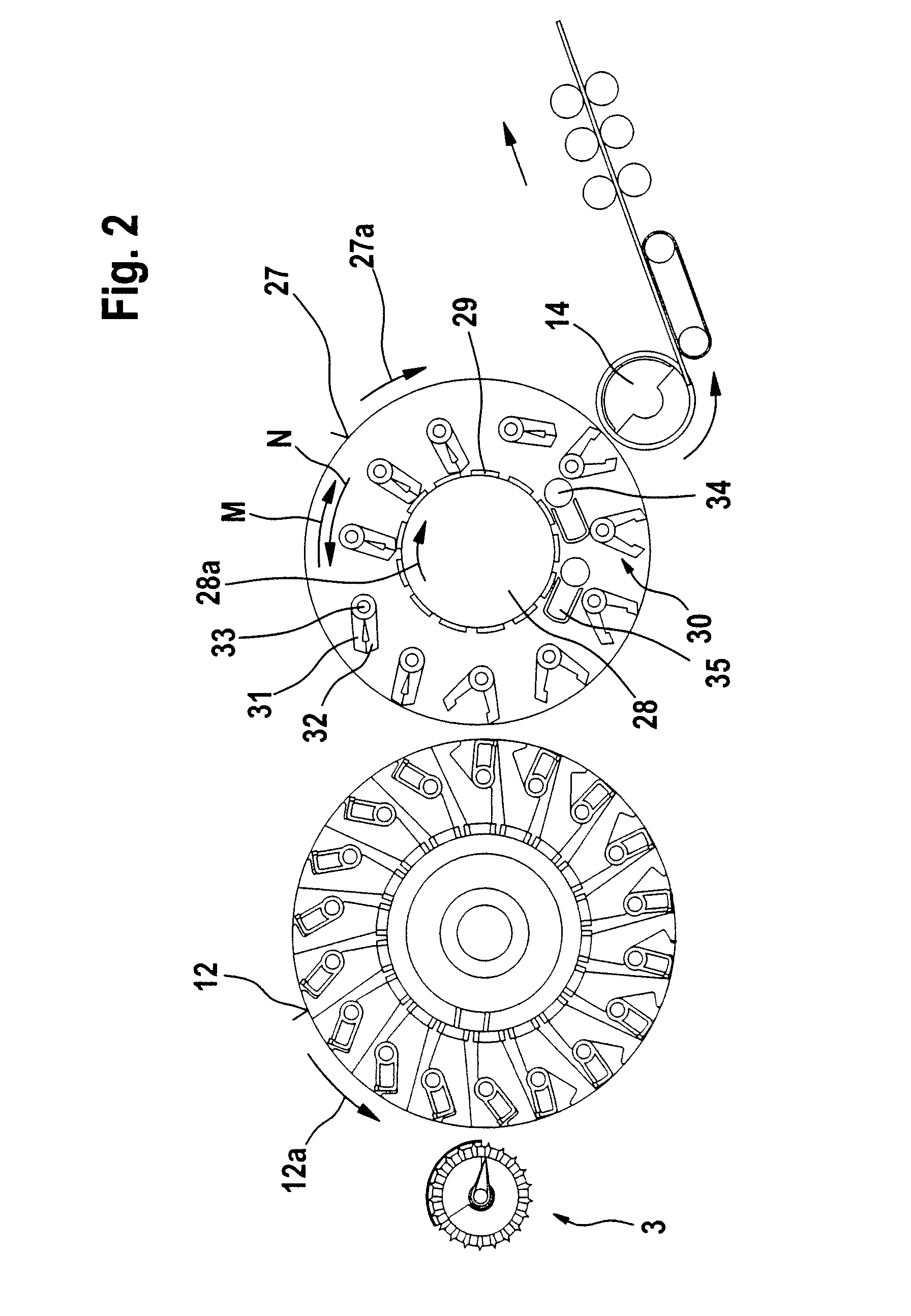
[0027]FIG. 1 shows a rotor combing machine 2 having a supply device 8, a first roller 12 (turning rotor), a second roller 15 (combing rotor), and a take-off device comprising a take-off roller 14. The directions of rotation of the rollers 12 and 15 are shown by curved arrows 12a and 15a, respectively. The rollers 12, 15 and 14 are arranged one after the other. Arrow A denotes the operating direction.

[0028]Referring to FIG. 1, the rotatably mounted first roller 12 is provided in the region of its outer periphery with a plurality of first clamping devices which extend across the width of the roller 12 and each consist of an upper nipper 19 (gripping element) and a lower nipper 20 (counter-element). In its one end region facing the centre point or the pivot axis of the roller 12, each upper nipper 19 is rotatably mounted on a pivot bearing 24a, which is attached to the roller 12. The lower nipper 20 is mounted on the roller 12 so to be fixed. The free end of the upper nipper 19 faces t...


PUM


Abstract

In an apparatus for the fibre-sorting or fibre-selection of a fibre bundle comprising textile fibres, especially for combing, clamping devices are provided which clamp the fibre bundle at a distance from its free end, and a mechanical arrangement is present which generates a combing action from the clamping site to the free end, in order to loosen and remove non-clamped constituents. To enable productivity to be substantially increased in a simple manner and an improved combed sliver to be obtained, downstream of the supply device there are arranged at least two rotatably mounted rollers, clamping devices being distributed spaced apart in the region of at least one said roller's periphery, and the arrangement for generating a combing action is inside the roller.

Description

CROSS REFERENCE TO RELATED APPLICATIONS[0001]This application claims priority from German Patent Application No. 10 2007 030 393.0 dated Jun. 29, 2007, German Utility Model No. 20 2007 010 686.6 dated Jun. 29, 2007, and German Patent Application No. 10 2008 004 096.7 dated Jan. 11, 2008, the entire disclosure of each of which is incorporated herein by reference.BACKGROUND OF THE INVENTION[0002]The invention relates to an apparatus for the fibre-sorting or selection of a fibre bundle comprising textile fibres, especially for combing, which is supplied by means of supply means to a fibre-sorting device, especially to a combing device. It is known in a combing device to provide clamping devices, which clamp the fibre sliver at a distance from its free end, mechanical means being present which generate a combing action from the clamping site to the free end of the fibre sliver in order to loosen and remove non-clamped constituents, such as, for example, short fibres, neps, dust and the ...

Claims


Application Information

Patent Timeline
IPC IPC(8): D01G19/00
CPCD01G19/08D01G19/10D01G19/16D01G19/12D01G19/105
Inventor BOSSMANN, JOHANNES
Owner TRUETZSCHLER GMBH & CO KG
Why Eureka
Try Eureka