Imaging reader with plural solid-state imagers for electro-optically reading indicia

a solid-state imager and imager technology, applied in the direction of instruments, sensing record carriers, visual presentations, etc., can solve the problems of slowing transaction processing, reducing productivity, and reducing the difficulty of blind-aiming symbols, so as to reduce the cost of imagers

Active Publication Date: 2009-01-01
SYMBOL TECH LLC
View PDF26 Cites 43 Cited by
  • Summary
  • Abstract
  • Description
  • Claims
  • Application Information

AI Technical Summary

Benefits of technology

[0013]One feature of this invention resides, briefly stated, in a reader for, and a method of, electro-optically reading indicia, comprising a housing and a plurality of solid-state imagers at the housing, for capturing light from the indicia along different fields of view. Each imager preferably comprises a two-dimensional, charge coupled device (CCD) array of submegapixel size, e.g., 752 pixels wide×480 pixels high, in order to reduce the costs of the imagers, as compared to supermegapixel arrays. Each imager includes an illuminator for illuminating the indicia with illumination light from illumination light sources, e.g., light emitting diodes (LEDs). A controller is operative for controlling each illuminator to illuminate the indicia, for controlling each imager to capture the illumination light returning from the indicia over an exposure time period to produce electrical signals indicative of the indicia being read, and for processing the electrical signals to read the indicia. Each illuminator is only operative during the exposure time period. Each imager is controlled to capture the light from the indicia during different exposure time periods to avoid mutual interference among the illuminators. At least one of the imagers captures the light from the indicia along a return axis, and its illuminator directs the illumination light along an illumination axis that is angled toward the return axis.
[0014]In accordance with one aspect of this invention, the imagers are commonly mounted on a circuit board. This assembly enables joint installation at, and joint removal from, the housing for ease of serviceability. Advantageously, each illuminator is commonly mounted on the same circuit board. The controller is also preferably commonly mounted on the circuit board. Thus, by mounting most, if not all, of the electrical components on the same board, field maintenance is simplified.
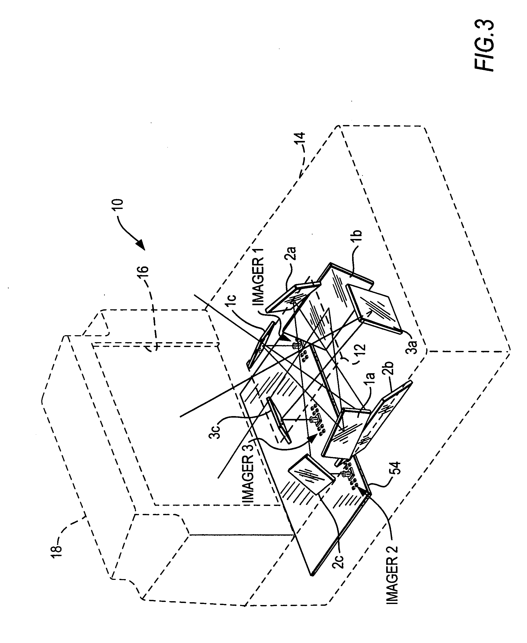
[0016]In still another aspect of the invention, the return illumination light travels along an optical path within the housing between a respective window and a respective imager for a distance of at least thirty-five centimeters. Folding optics, such as mirrors, are operative for folding the optical path within the housing. Also, non-rotationally symmetrical optics, such as mirrors and lenses, are operative for optically modifying the field of view of at least one imager to correspond with at least one of the dimensions of the window. The optical elements within the housing, for folding at least one of the optical paths, are preferably commonly mounted on a support, particularly an enclosure that keeps dust, dirt, moisture, and like contaminants from reaching these optical elements. This support enables joint installation of the optical elements at, and joint removal of the optical elements from, the housing for ease of serviceability. The non-rotationally symmetrical optics for optically modifying the field of view of at least one of the imagers are preferably mounted on the respective imager.
[0017]By way of numerical example, the generally horizontal window in a conventional laser-based bi-optical workstation measures about four inches in width by about six inches in length, and the generally vertical window measures about six inches in width by about ten inches in length. The field of view of an imager capturing illumination light from the imager through a respective window does not inherently have these dimensions at the respective window and, hence, the field of view must be modified so that it matches the dimensions of the respective window at the respective window, thereby enabling indicia to be reliably read when located anywhere at the respective window, as well as within a range of working distances therefrom.
[0021]Hence, an all imager-based reader has been proposed that eliminates the need for ten to twelve imagers in order to read indicia that could be positioned anywhere on all six sides of a product. The cost of all the imagers, as well as the cost of each imager, has been reduced to an acceptable level. The all imager-based reader matches, or at least is comparable to, the working range, processing speed, productivity and performance of the laser-based reader. In the case of a bi-optical workstation having dual windows, the all imager-based reader uses similar window sizes and the indicia is able to be scanned anywhere across the windows and over a comparable working range as that of the laser-based reader, so that operators can achieve the high scanning productivity they have come to expect without any need to learn a new scanning technique.

Problems solved by technology

In typical “blind-aiming” usage, it is not uncommon for the operator to repeatedly swipe or present a single symbol several times before the symbol is successfully read, thereby slowing down transaction processing and reducing productivity.
The blind-aiming of the symbol is made more difficult because the position and orientation of the symbol are variable.

Method used


Image

  • Imaging reader with plural solid-state imagers for electro-optically reading indicia
  • Imaging reader with plural solid-state imagers for electro-optically reading indicia
  • Imaging reader with plural solid-state imagers for electro-optically reading indicia

Examples


Embodiment Construction

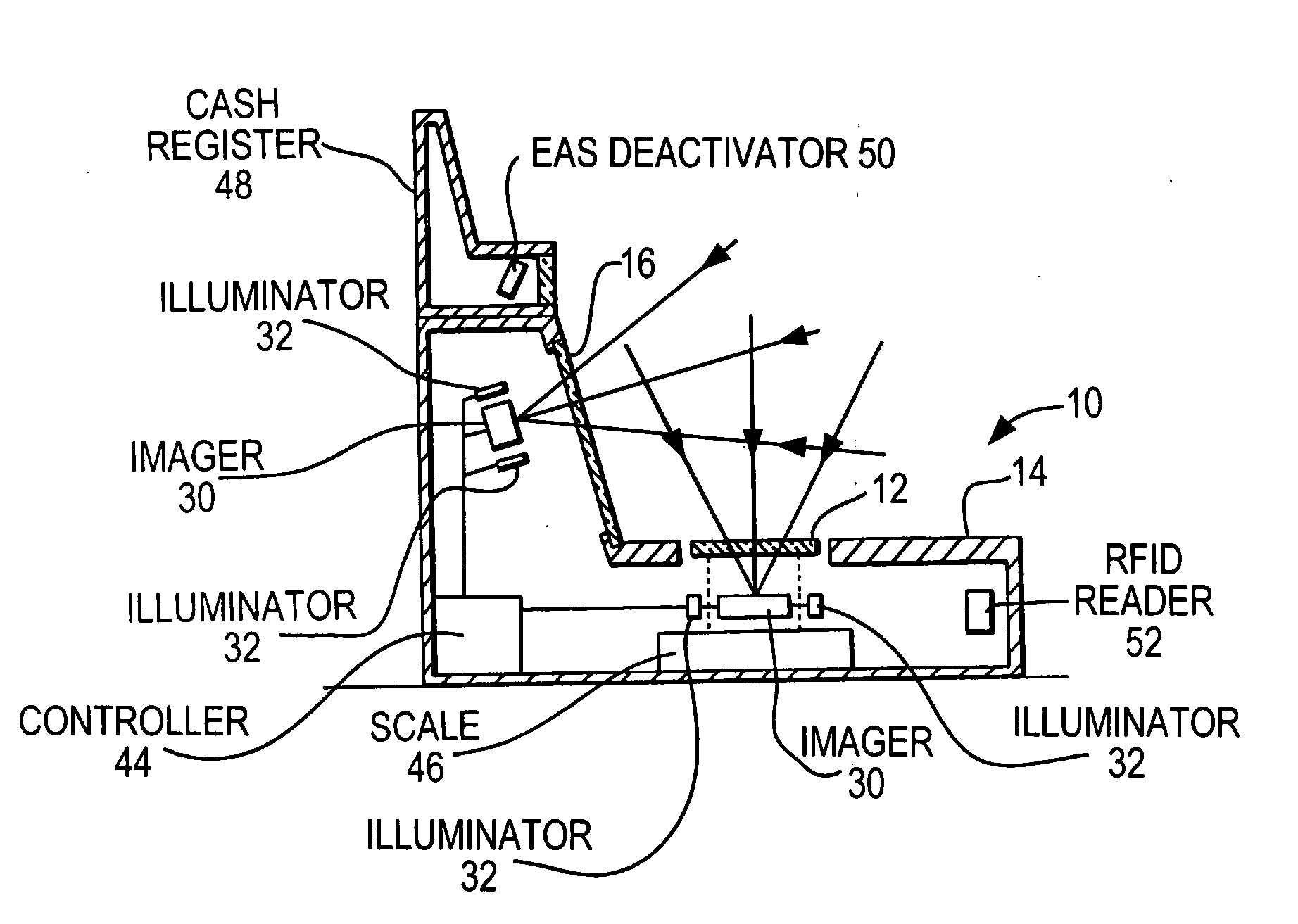
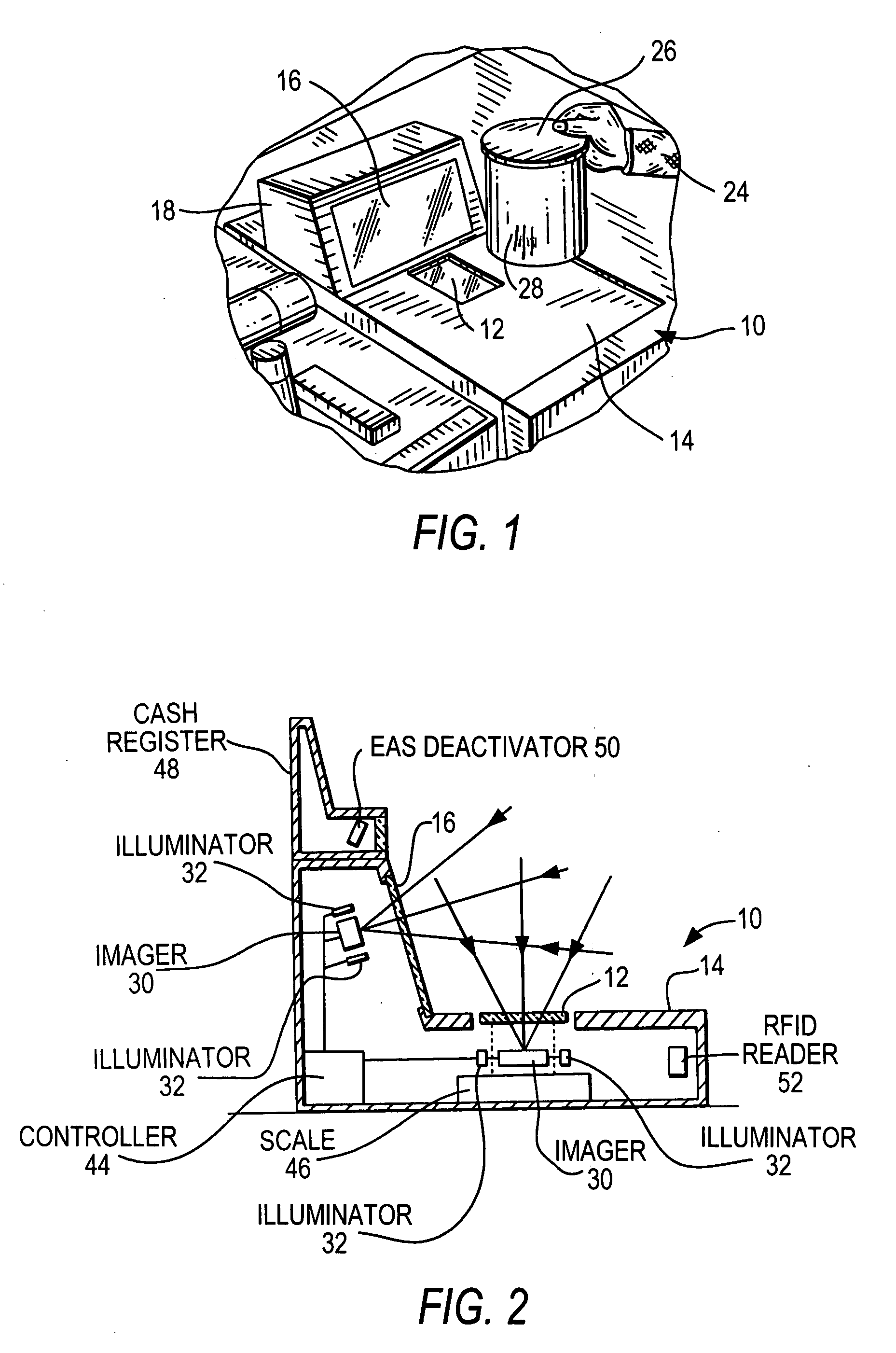
[0027]FIG. 1 depicts a dual window, bi-optical, point-of-transaction workstation 10 used by retailers to process transactions involving the purchase of products bearing an identifying target, such as the UPC symbol described above. Workstation 10 has a generally horizontal window 12 set flush with, or recessed into, a countertop 14, and a vertical or generally vertical (referred to as “vertical” or “upright” hereinafter) window 16 set flush with, or recessed into, a raised housing portion 18 above the countertop.

[0028]As schematically shown in FIG. 2, a plurality of solid-state imagers 30, each including an illuminator 32, are also mounted at the workstation, for capturing light passing through either or both windows from a target which can be a one- or two-dimensional symbol, such as a two-dimensional symbol on a driver's license, or any document, as described below. Each imager 30 is a solid-state area array, preferably a CCD or CMOS array, of submegapixel size. Each imager 30 pre...


PUM


Abstract

A plurality of solid-state imagers is mounted in a reader, such as a bi-optical, dual window, point-of-transaction workstation, for capturing images along different fields of view of diverse targets useful for customer identification, customer payment validation, operator surveillance, and coded indicia. The imagers are commonly mounted on a circuit board for joint installation at, and joint removal from, the reader for ease of serviceability.

Description

BACKGROUND OF THE INVENTION[0001]Flat bed laser readers, also known as horizontal slot scanners, have been used to electro-optically read one-dimensional bar code symbols, particularly of the Universal Product Code (UPC) type, at a point-of-transaction workstation in supermarkets, warehouse clubs, department stores, and other kinds of retailers for many years. As exemplified by U.S. Pat. No. 5,059,779; U.S. Pat. No. 5,124,539 and U.S. Pat. No. 5,200,599, a single, horizontal window is set flush with, and built into, a horizontal countertop of the workstation. Products to be purchased bear an identifying symbol and are typically slid across the horizontal window through which a multitude of scan lines is projected in a generally upwards direction. When at least one of the scan lines sweeps over a symbol associated with a product, the symbol is processed and read.[0002]The multitude of scan lines is generated by a scan pattern generator which includes a laser for emitting a laser beam...

Claims


Application Information

Patent Timeline
Patent Type & Authority Applications(United States)
IPC IPC(8): G06K7/10
CPCG06K7/10801G06K7/10722
Inventor BARKAN, EDWARDDRZYMALA, MARKVINOGRADOV, IGOR
Owner SYMBOL TECH LLC
Why Eureka
Try Eureka