Axial air gap type electric motor

Inactive Publication Date: 2009-01-01
FUJITSU GENERAL LTD
View PDF9 Cites 9 Cited by
  • Summary
  • Abstract
  • Description
  • Claims
  • Application Information

AI Technical Summary

Benefits of technology

[0019]According to the second embodiment of the invention, because one of the bearings is installed in the inner circumferential space of the stator, even if a shock is imposed externally, no damage occurs. Because another bearing part is arranged near the load, even if a force is added to a radial direction in the rotor output axle, the force can be reduced in comparison with the conventional one. Moreover, because the interval between the bearings becomes larger than the conventional one, the force imposed on both the bearings can be reduced. These effects enable to prevent a damage of the bearing parts and prolong the lifetime.
[0020]According to the third embodiment of the invention, because a pre-compression is imposed on one of the bearings by biasing the rotor output axle to the axial direction and the ball contact face inside the ball bearing can be maintained constantly, the ball doesn't move violently and a long lifetime of the bearings can be thus realized.
[0021]According to the fourth embodiment of the invention, because the direction to bias the rotor output axle is

Problems solved by technology

When a force is added to the direction where such axles incline, a strong force is imposed on the ball bearing of the bearing part, which may caus

Method used


Image

  • Axial air gap type electric motor
  • Axial air gap type electric motor
  • Axial air gap type electric motor

Examples


Embodiment Construction

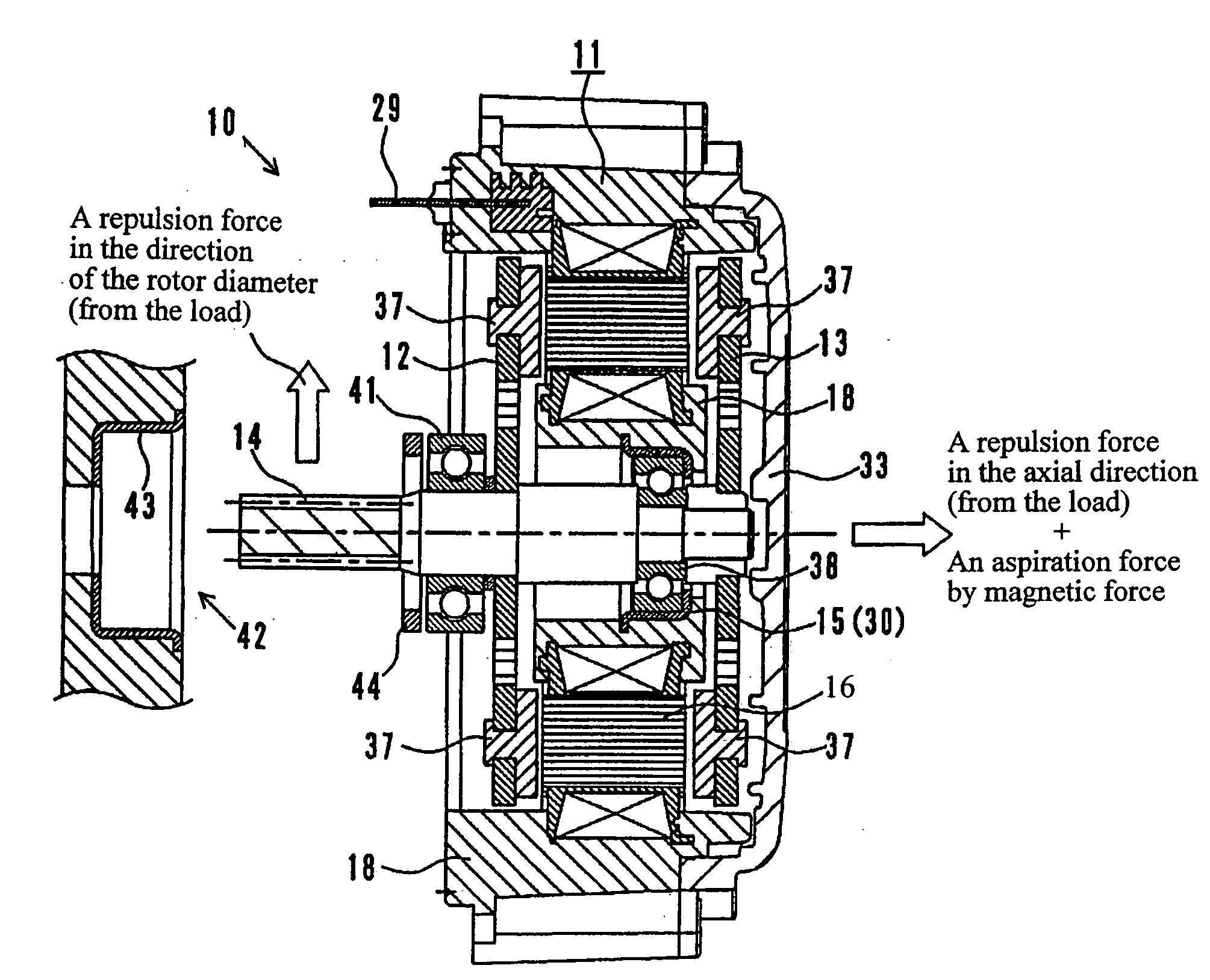
[0039]The axial air gap type electric motor of the present invention comprises a stator and two rotors each of which is configured almost with a discoid shape and which are arranged on a common rotation axle as facing one another with a fixed gap therebetween, wherein the stator has a stator core comprising multiple pole members connected annularly, one of bearings for fixing the rotor output axle is installed inside the stator configured annularly and another bearing is installed on the rotor output axle between the outside of the rotor and the load connected.

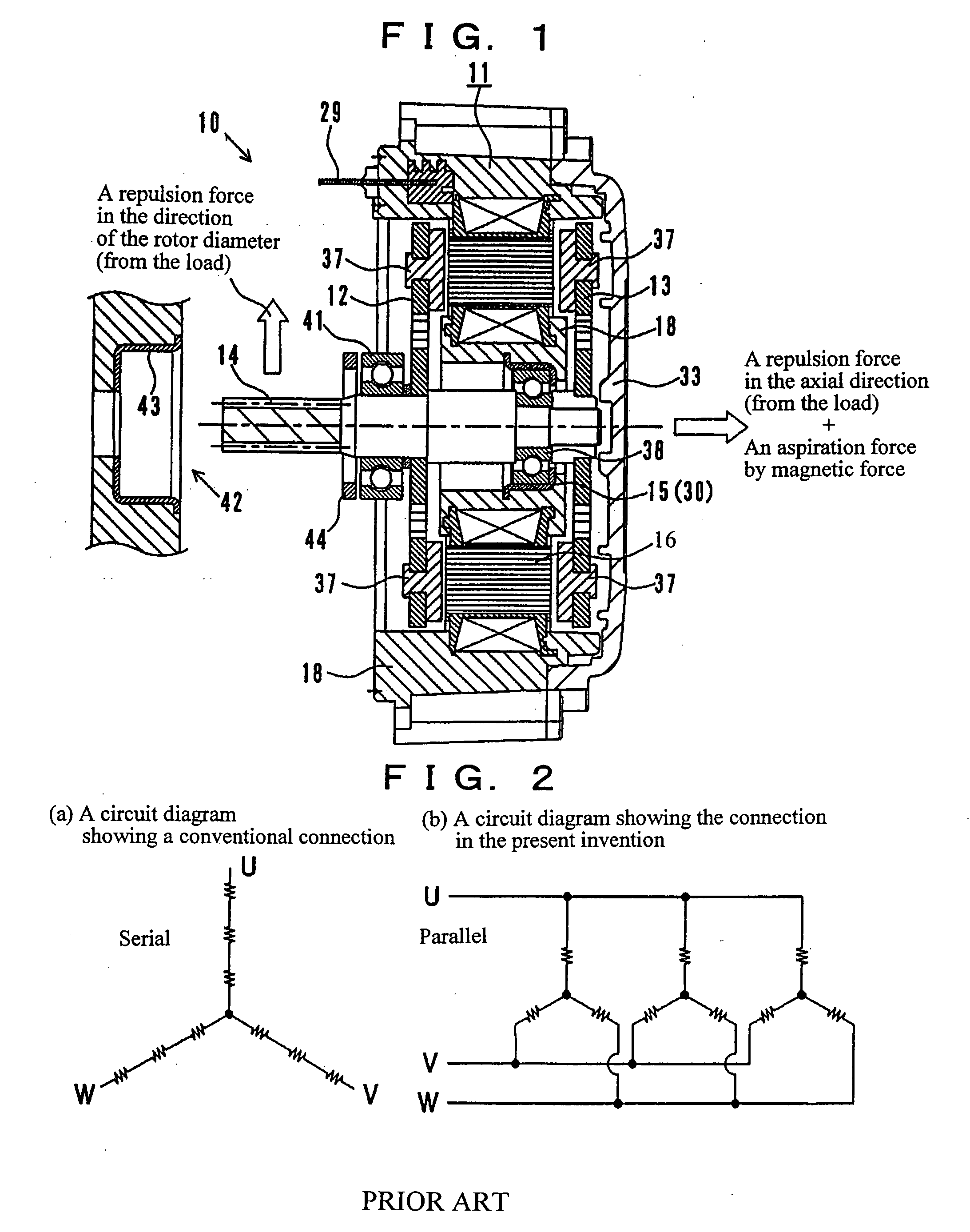
[0040]FIG. 1 is an outlined cross-sectional diagram of the internal configuration of an axial air gap type electric motor of the present invention. As shown in FIG. 1, the axial air gap type electric motor 10 comprises a rough discoid stator 11 and a pair of rotors 12 and 13 arranged with a fixed gap at both the sides of the stator 11 as facing each other, wherein the rotors 12 and 13 share a common rotor output axle 14, and t...


PUM


Abstract

An axial air gap type electric motor is constructed such that even if a relatively large force is added in the vertical direction to the rotor output, the bearings are protected against damage. The axial air gap type electric motor includes a stator and two rotors each of which is configured almost with a discoid shape and which are arranged as facing one another on a common rotation axle with a fixed gap being present therebetween. The stator has a stator core comprising multiple pole members connected annularly. One of the bearings for fixing the rotor output axle is installed inside the stator configured annularly and another bearing is installed on the rotor output axle between the outside of said rotor and the load connected.

Description

BACKGROUND OF THE INVENTION[0001]The present invention relates to an axial air gap type motor comprising a stator and a rotor which are formed almost with a discoid shape and arranged as facing each other at a fixed gap on a common rotation axle. More specifically, the present invention relates to a configuration of the axial air gap type motor for realizing a torque up without an increase of the coil diameter.[0002]Conventionally, axial air gap motors (axial-direction gap type motors) exist as one of motor types. The axial air gap motors are motors in which rotors are arranged at a discoid stator as facing at a fixed gap in the axial direction and the length of the axial direction can be shortened in comparison with radial gap type motors, being advantageous by being able to make the motors thinner types. For example, as for this axial air gap motor, this applicant has already applied for the patent document 1 in which the purpose is to conduct the assembly works of the stators inc...

Claims


Application Information

Patent Timeline
IPC IPC(8): H02K21/24
CPCH02K3/522H02K21/24H02K7/085
Inventor KOJIMA, TOMONORITANNO, TOSHIAKIMAEYAMA, KENMATSUZAKI, HIROKAZU
Owner FUJITSU GENERAL LTD
Why Eureka
Try Eureka