Adjustable Width Vanity and Method for Securing an Adjustable Width Vanity

Inactive Publication Date: 2009-01-01
DECOLAV
View PDF44 Cites 2 Cited by
  • Summary
  • Abstract
  • Description
  • Claims
  • Application Information

AI Technical Summary

Benefits of technology

[0020]In accordance with a further object of the invention, the support has a flange for limiting travel of the support relative to the bracket. The flange abuts the bracket when the side unit is mov

Problems solved by technology

Unfortunately, in many hotels the size of the stalls is not universal.
The fixture support is unable to telescope to accommodate different heights of roofs.
The adjustable vanity is unable to telescope to accommodate different heights of roofs.
The vertically adjustable lavatory assembly is unable to telescope to accom

Method used


Image

  • Adjustable Width Vanity and Method for Securing an Adjustable Width Vanity
  • Adjustable Width Vanity and Method for Securing an Adjustable Width Vanity
  • Adjustable Width Vanity and Method for Securing an Adjustable Width Vanity

Examples


Example

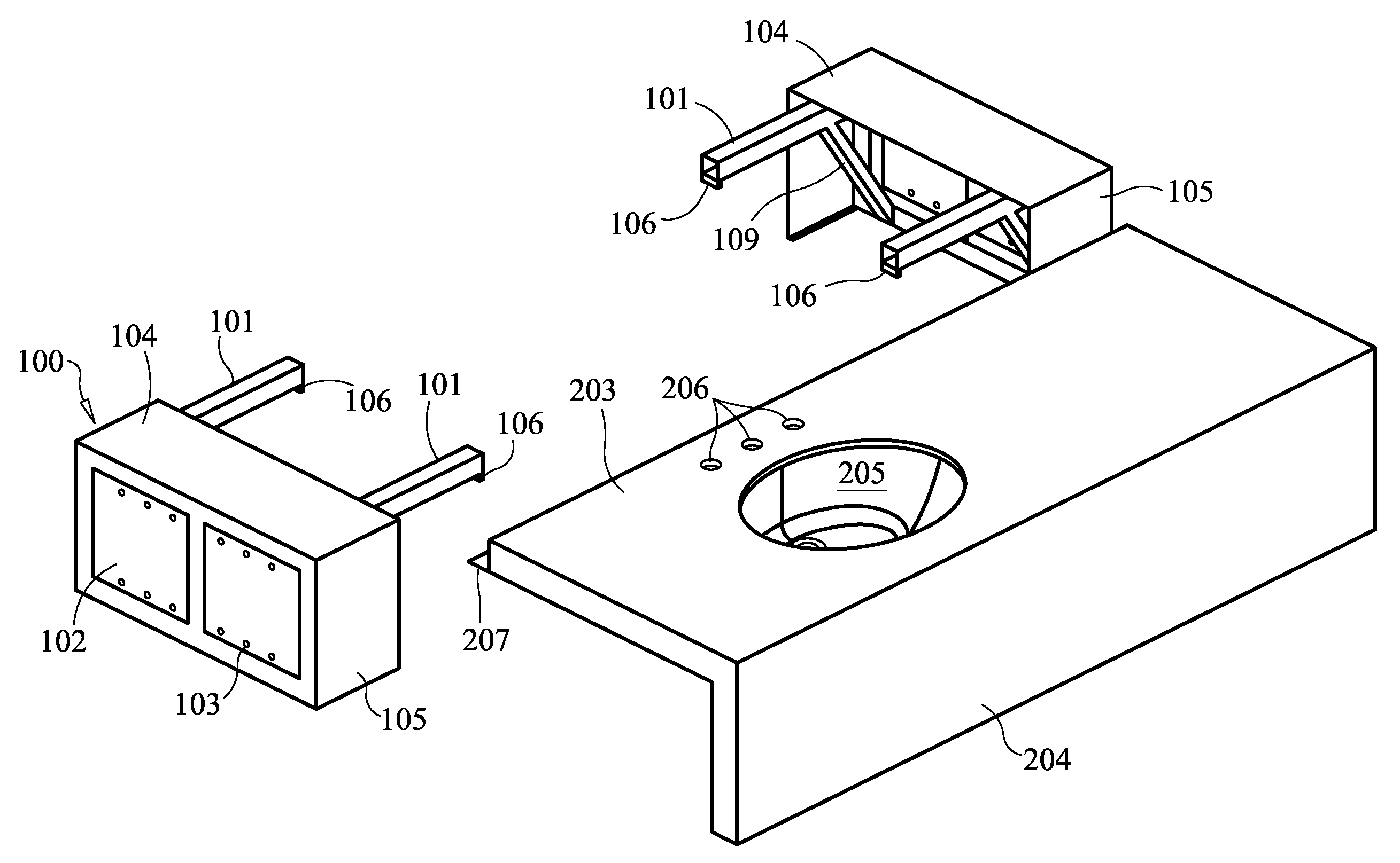
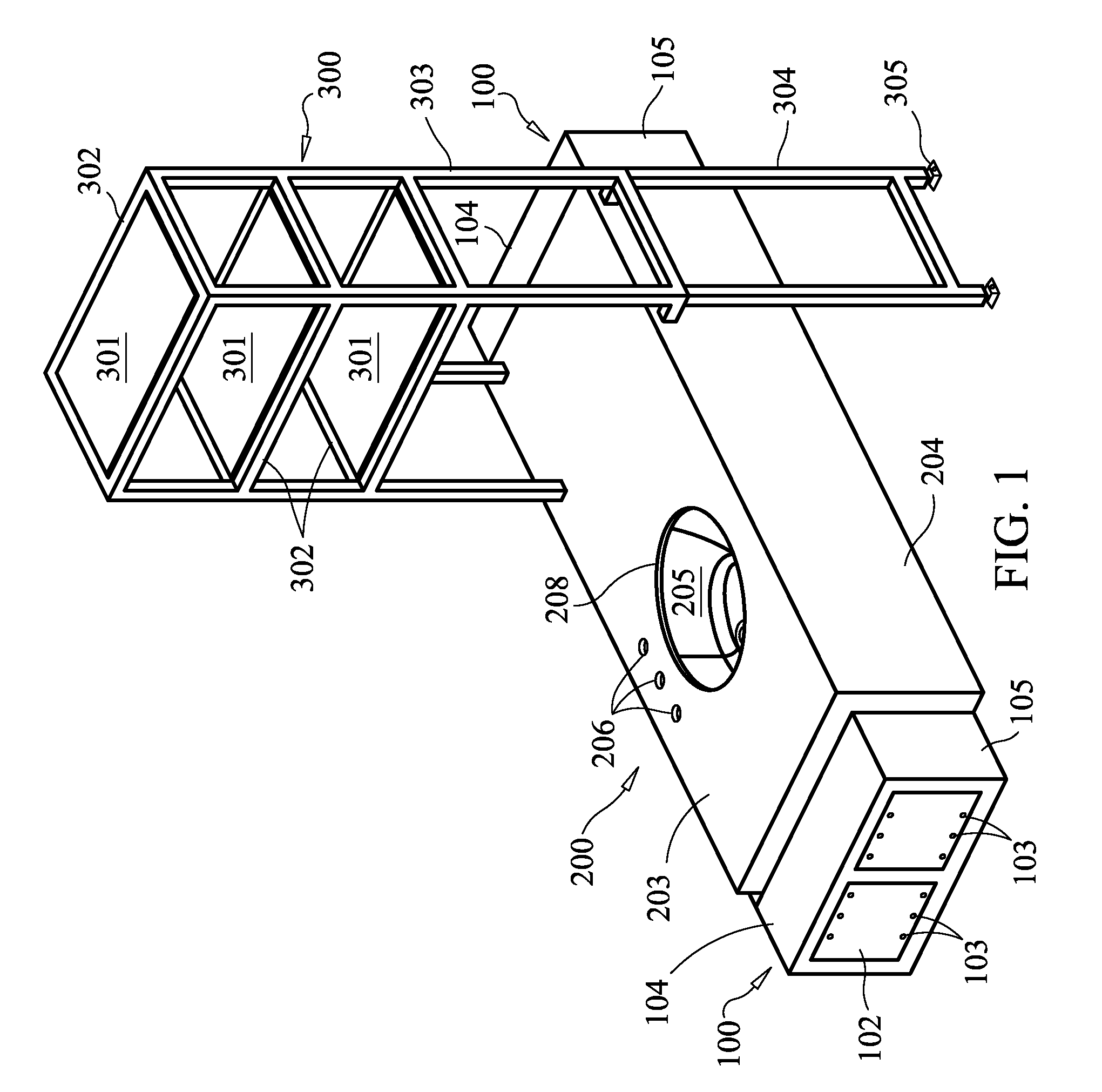
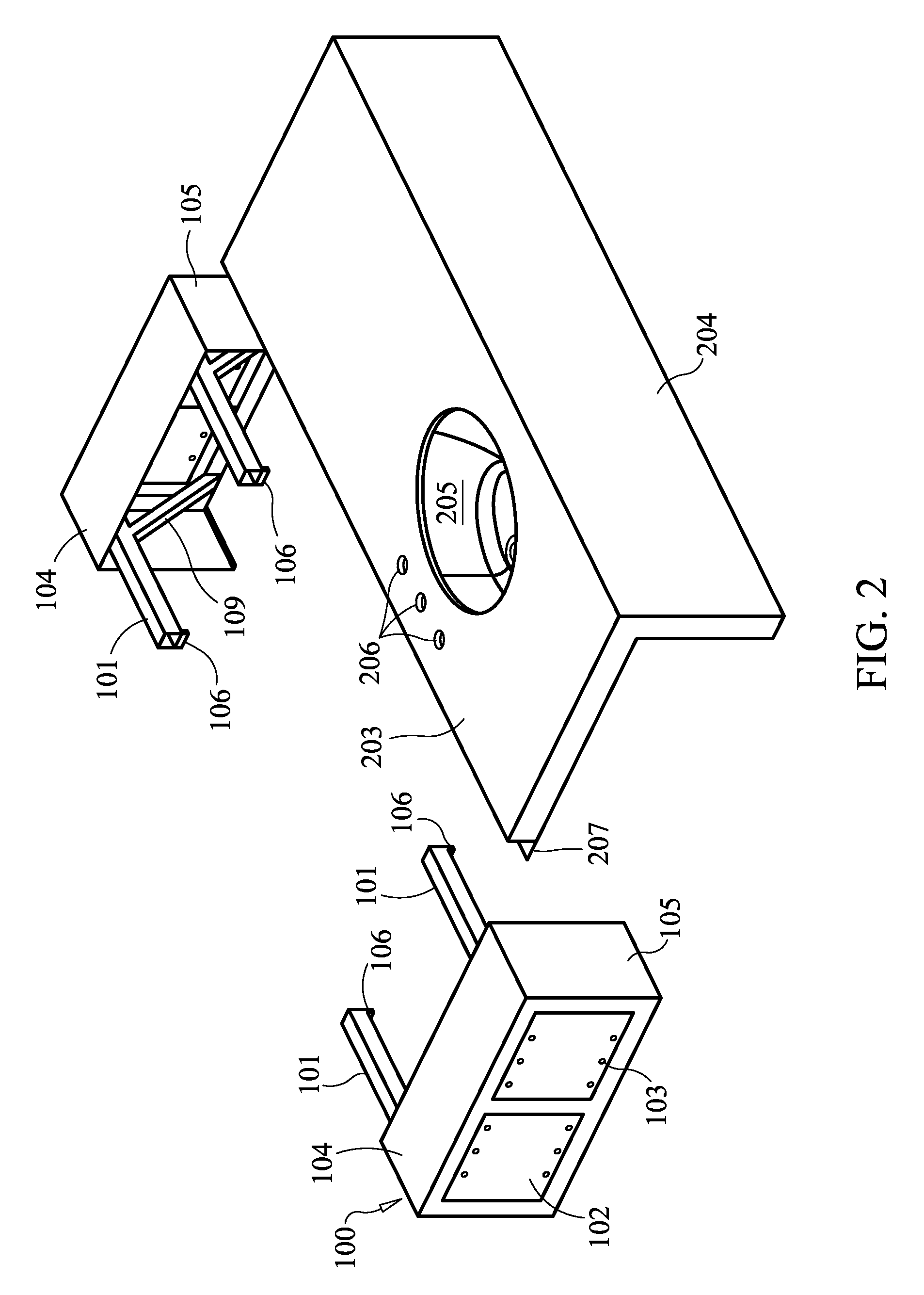
[0036]Referring now to the figures of the drawing in detail and first, particularly, to FIGS. 1-3 thereof, there is seen an adjustable width vanity. The adjustable width vanity includes a main body 200 and two laterally opposed (i.e. a left and a right) side units 100. A shelf assembly 300 can be included as well.

[0037]The main body 200 includes a countertop 203. The countertop 203 has a washbasin cutout 208 formed therein. A washbasin 205 is attached beneath the countertop 203. Alternatively, a drop-in sink or a vessel that rests on the countertop 203 could be used. Fixture cutouts 206 are formed in the countertop 203. Preferably, there are three fixture cutouts 206: one for a faucet, one for a hot-water knob, and one for a cold-water knob. A counter face 204 (also known as a valance) is connected to a front edge of the countertop 203. The counter face 204 hides plumbing and the side units 100 from sight. A lip 207 is disposed along a rear edge of the main body 200. The lip 207 abu...


PUM


Abstract

An adjustable width vanity has a main body that can be positioned relative to a side unit so that the overall width of the vanity can be adjusted to fit within a variety of stalls having different widths.

Description

CROSS-REFERENCE TO RELATED APPLICATIONS[0001]This application claims the benefit of U.S. Provisional Application No. 60 / 946,660, filed Jun. 27, 2007.BACKGROUND OF THE INVENTION[0002]1. Field of the Invention[0003]The invention relates to bathroom vanities and in particular to an adjustable width vanity and method for securing same.[0004]2. Description of the Related Art[0005]Bathroom vanities are the countertops used typically with bathroom sinks and mirrors. Bathroom vanities, particularly those in hotels, are placed in a stall that has a left wall, a right wall, and rear wall.[0006]In hotels, there can be a need to install thousands of similar vanities into the many rooms. When the size of the stall is universal, one sized vanity can be manufactured in quantity for discount and installed in all of the stalls.[0007]Unfortunately, in many hotels the size of the stalls is not universal. That is, the stalls may come in a range of widths. Despite the different sizes, hoteliers are stil...

Claims


Application Information

Patent Timeline
IPC IPC(8): A47K1/05
CPCE03C1/322A47K1/05
Inventor TOPAN, YUNUSMAYER, ROBERT H.
Owner DECOLAV
Why Eureka
Try Eureka