Double headed drill bit for a continuous coal mining machine

Inactive Publication Date: 2018-06-07
ALLIANCE COAL LLC
View PDF4 Cites 5 Cited by
  • Summary
  • Abstract
  • Description
  • Claims
  • Application Information

AI Technical Summary

Benefits of technology

[0016]The cutting element for a continuous mining machine may further include a cylindrical end support configured to be inserted into the lower end of the sleeve. The cylindrical end support may have an outer surface that is configured to be rotatably received within the circular opening in the annular sleeve. The outer surface of the cylindrical end support also includes an annular groove configured to removably receive a clip therein for limiting the travel of the end suppor

Problems solved by technology

With each rotary drum member 12 carrying several dozen cutting elements 20, and with the drill bits 26 being subject to significant wear, there may be considerable cost in purchasing drill bits associated with a con

Method used


Image

  • Double headed drill bit for a continuous coal mining machine
  • Double headed drill bit for a continuous coal mining machine
  • Double headed drill bit for a continuous coal mining machine

Examples


Example

[0028]For purposes of promoting and understanding of the principles of the invention, reference will now be made to the embodiments illustrated in the drawings and specific language will be used to describe the same. It will nevertheless be understood that no limitation of the scope of the invention is thereby intended. The invention includes any alterations and further modifications in the illustrated devices and described methods and further applications of the principles of the invention that would normally occur to one skilled in the art to which the invention relates.

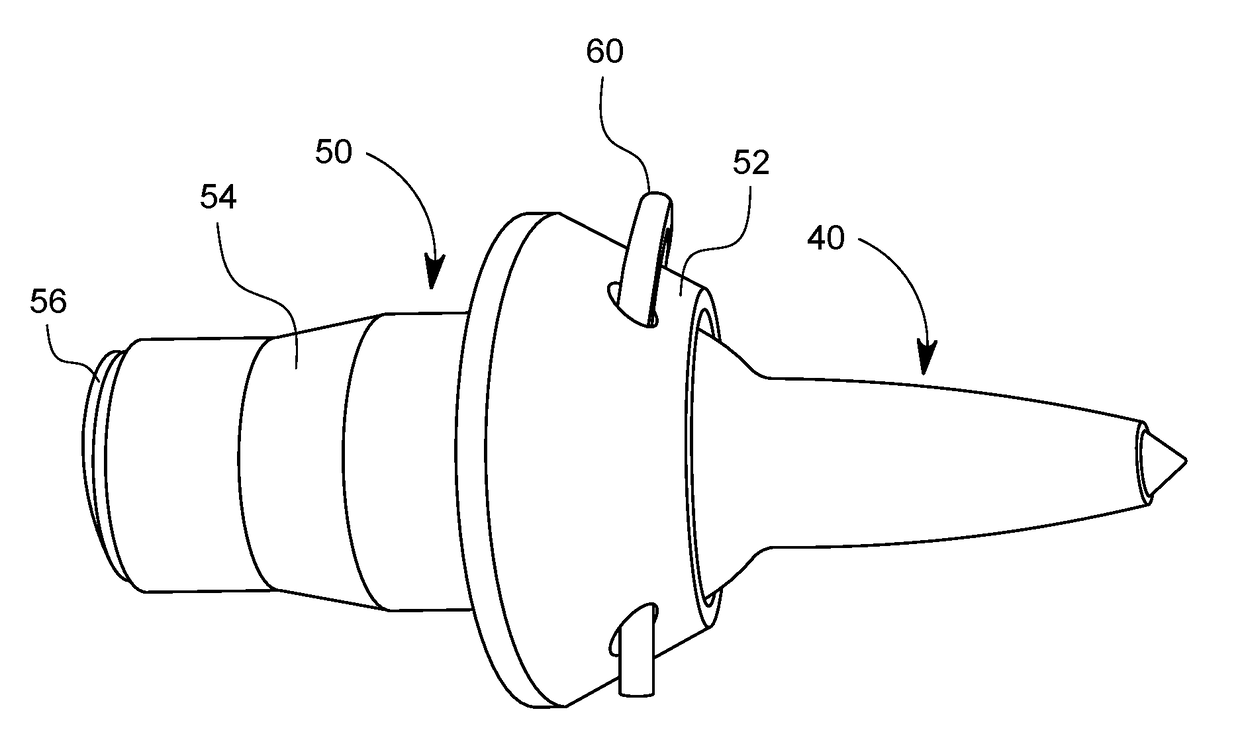
[0029]As best shown in FIG. 4 and FIG. 5, one presently preferred embodiment of the invention comprises an improved drill bit 40, sleeve 50, retention clip 60 and end support 70. According to this embodiment of the invention, the improved drill bit 40 includes a first tapered bit portion 42a at a first end thereof and a second tapered bit portion 42b at a second end thereof. As with the prior art bit, each taped bi...


PUM


Abstract

A double headed drill bit for a cutting element carried on a rotary drum member of a continuous mining machine is provided according to the invention. The drill bit is formed from a length of hardened material and includes a first tapered bit portion extending from a point located at a first end of the length of hardened material toward a mid-portion of the length of hardened material, and a second tapered bit portion extending from a point located at a second end of the length of hardened material toward the mid-portion of the length of hardened material. The drill bit is removably positioned within the central opening of an annular sleeve located in a block member mounted on the rotary drum member. One of the first tapered bit portion or second tapered bit portion extends outwardly from the annular sleeve and the other of the first tapered bit portion or second tapered bit portion extends into the shank portion the annular sleeve. Positive retention means for securing the drill bit against longitudinal movement within the annular sleeve are also provided in the form of a retaining clip which engages an annular groove at the mid-portion of the drill bit.

Description

BACKGROUND OF THE INVENTIONField of the Invention[0001]The present invention relates to drill bits used in underground coal mining machines. More specifically, the present invention relates to a drill bit having two opposing bit heads and a new positive retention system for holding the bit in a sleeve.Description of the Related Art[0002]Continuous mining machines with drum type dislodging means are well-known and have been used for many years in the underground mining industry. A typical drum-type continuous mining machine 10 is shown in FIG. 1. The mining machine 10 includes a rotary drum member 12 carried on the forward end of a boom 14 of the continuous mining machine 10. The rotary drum member 12 carries multiple cutting elements 20, which are the subject matter of the present invention. A prior art cutting element 20 as best shown in FIG. 2 and FIG. 3 includes a block 22 which is mounted on the rotary drum member 12. The block 22 has a substantially cylindrical opening in a fac...

Claims


Application Information

Patent Timeline
IPC IPC(8): E21C35/197E21C25/10
CPCE21C25/10E21C35/197
Inventor HILL, TOD
Owner ALLIANCE COAL LLC
Why Eureka
Try Eureka