

Mechanical lash ring for a switchable valve train member
- Summary
- Abstract
- Description
- Claims
- Application Information
AI Technical Summary
Benefits of technology
Problems solved by technology
Method used
Image

Examples
Embodiment Construction
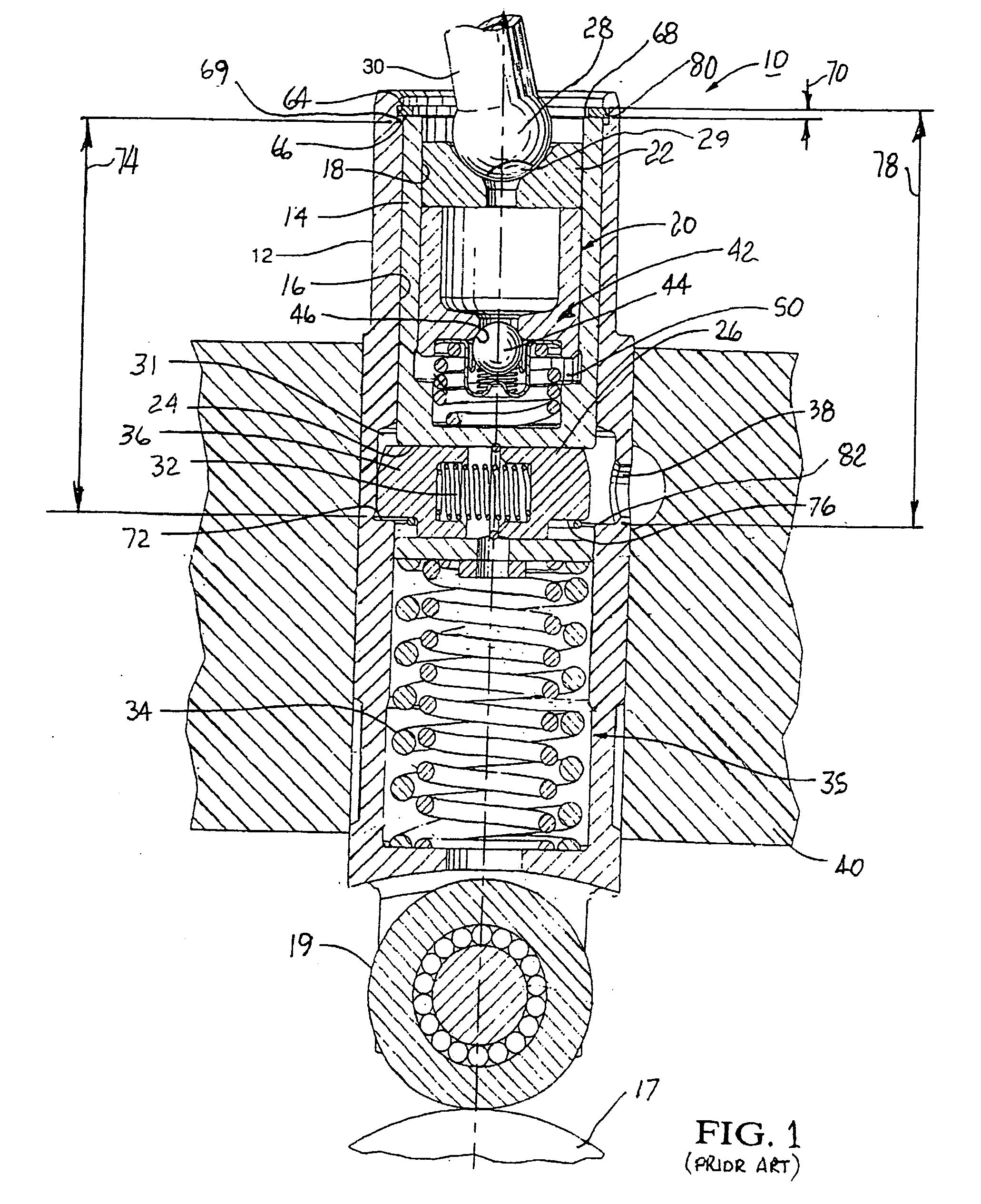
[0024]Referring to FIG. 1, a prior art DHVL 10 is shown, substantially as disclosed in U.S. Pat. No. 6,578,535, the relevant disclosure of which is incorporated herein by reference. DHVL 10 has a generally cylindrical body 12. A pin housing 14 is slidably disposed within a first axial bore 16 in body 12. Pin housing 14 itself has a second axial bore 18 for slidably receiving a plunger 20 having a pushrod seat 22 for receiving an end 28 of a valve actuator such as pushrod 30 in cam-in-block engine valve train (not shown). Pin housing 14 has a transverse bore 24 slidably receivable of two opposed locking pins 26 separated by a pin-locking spring 28 disposed in compression therebetween. First axial bore 16 in body 12 is provided with a an engagement feature such as circumferential groove 31 for receiving the outer ends of locking pins 26, thrust outwards by spring 28 when pins 26 are axially aligned with groove 31. In such configuration, DHVL 10 is in valve-activation mode. (FIG. 1 is ...
PUM
 Abstract
Description
Claims
Application Information