
Pipe Core Sampling and Tapping Apparatus

Active Publication Date: 2019-06-13
HYDRA STOP LLC
View PDF16 Cites 2 Cited by
  • Summary
  • Abstract
  • Description
  • Claims
  • Application Information

AI Technical Summary

Benefits of technology

The patent describes a core sampling and tapping assembly for mounting to a cylindrical pipe. The assembly includes a nozzle, a tapping mandrel, a pilot bit, and a core cutter. The tapping mandrel is inserted into the nozzle and includes a mandrel plate attached to a mandrel shaft. A centering tool is used to align the pilot bit and the core cutter with the outer surface of the pipe. The assembly also includes a mandrel adaptor for securely attaching the core cutter to the mandrel plate. The technical effects of this assembly include improved alignment of the pilot bit and the core cutter with the pipe, simplified installation, and improved efficiency in collecting core samples.

Problems solved by technology

For example, when a shutdown is required in a municipal water system, a significant portion of a supply area may be deprived of water service.
Accordingly, in addition to the inconvenience to residents, schools, hospitals, commercial and / or industrial facilities may have to be shut down until water service is restored.
However, many municipalities, industrial plants and other commercial installations have incomplete, outdated or inaccurate records for the network of pipes which make it difficult to determine certain pipe characteristics such as but not limited to, size, material, class or other such specification.
However, determination of pipe class and internal pipe geometry may require use of expensive pipe imaging and gauging equipment (e.g., ultrasonic, radiation or other such imaging technology), drilling and tapping multiple holes in the pipe or even removing an entire section of pipe for closer inspection.
However, the tapping device of the '605 patent does not first provide a core cutter which may retrieve a core sample to determine unknown characteristics of the main and subsequently provide a size-on-size cutter to form the new tap in the main.
Furthermore, the tapping device of the '605 patent is not interchangeable for particular application needs.

Method used


Image

  • Pipe Core Sampling and Tapping Apparatus
  • Pipe Core Sampling and Tapping Apparatus
  • Pipe Core Sampling and Tapping Apparatus

Examples


Embodiment Construction

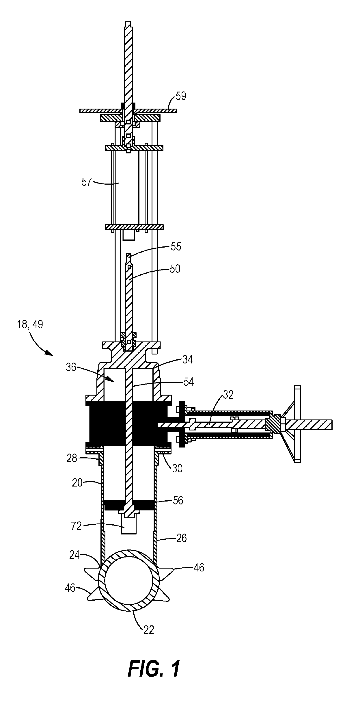
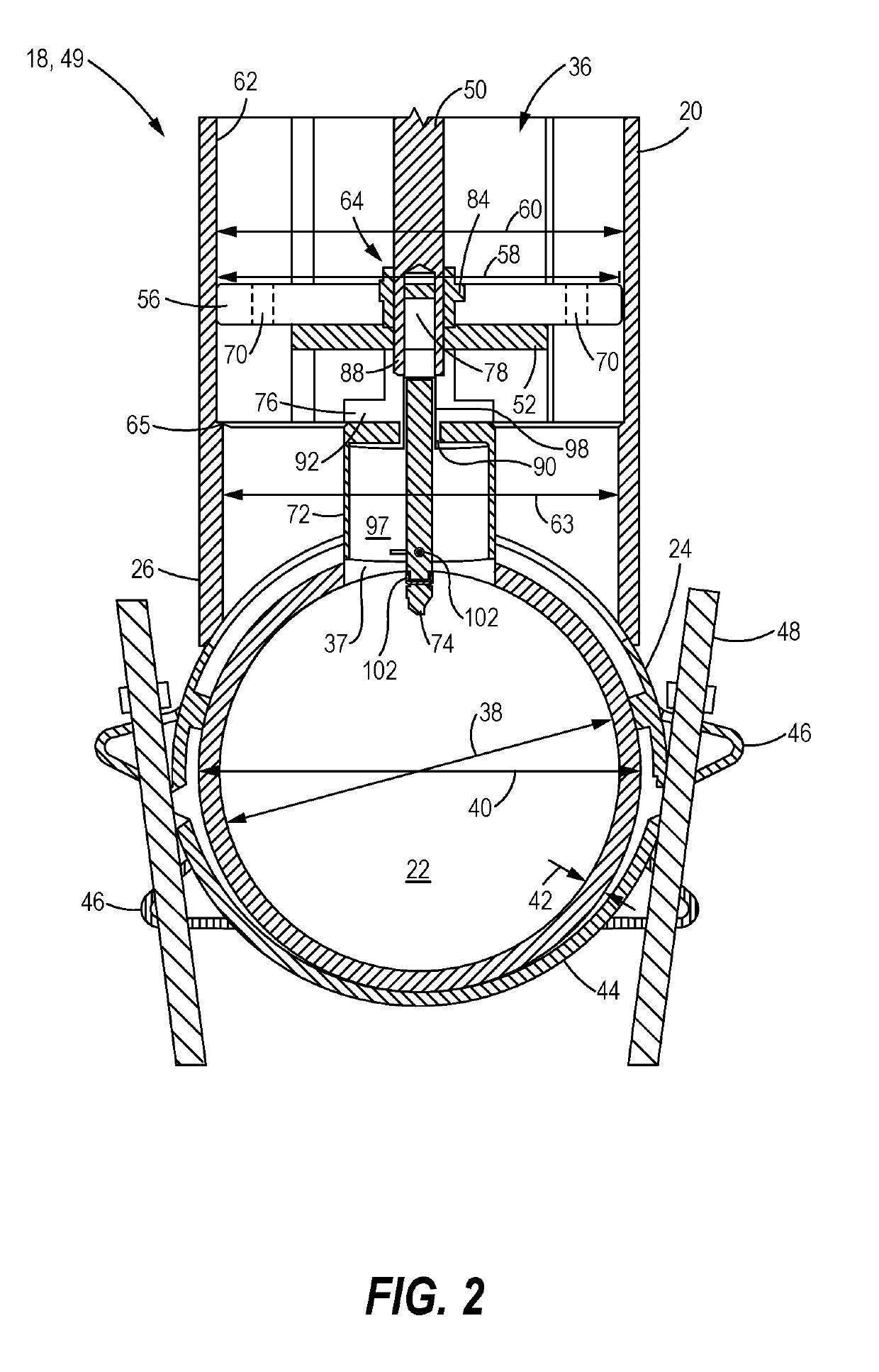
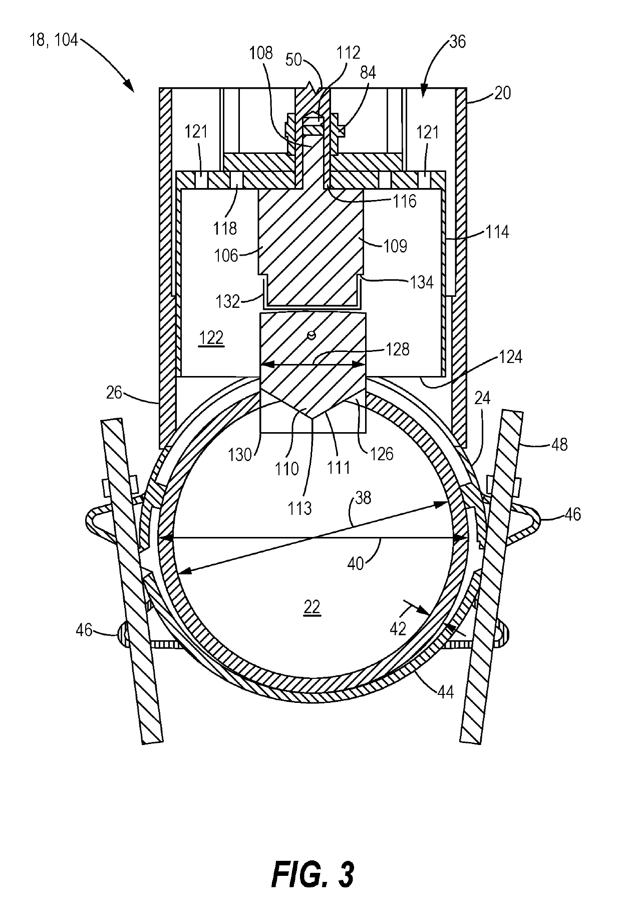
[0035]FIG. 1 is a cross-sectional view of a core sampling and tapping assembly 18 that includes a nozzle 20 mounted to a pressurized section of a pipe or conduit 22 such as but not limited to, a municipal water main, oil pipeline, natural gas pipeline or other such fluid conduit. In an embodiment, the nozzle 20 is attached to the section of pipe 22, or attached in close proximity to the section of pipe 22, that is in need of inspection and / or repair. Moreover, in some instances the exact size and characteristics of the pipe 22 may not be readily known. As a result, the nozzle 20 is coupled to the pipe 22 in order to conduct further inspection which helps determine characteristics such as but not limited to, the outer diameter, inner diameter, wall thickness, or other such characteristics of the pipe 22. For example, in order to install, repair, or replace a valve in the section of pipe 22 the exact dimensions (e.g., diameter and wall thickness) of the pipe 22 must first be determine...


PUM

PropertyMeasurementUnit
Thicknessaaaaaaaaaa
Diameteraaaaaaaaaa

Abstract

A core sampling and tapping assembly is disclosed that may be mounted to a cylindrical pipe. The assembly includes a nozzle having an interior portion extending between an open distal end and a proximal end. The proximal end sealed to an upper saddle member and the upper saddle member coupled to a lower saddle member to clamp the pipe in between. The assembly further includes a tapping mandrel including a mandrel plate, the tapping mandrel extending through the interior portion and a core cutter fixedly coupled to the mandrel plate. The assembly further includes a pilot bit coupled to the mandrel plate and disposed within an interior cavity of the core cutter. The tapping mandrel adjacently aligns the core cutter and the pilot bit with an outer surface of the pipe and subsequently rotates the pilot bit and core cutter to collect a core sample from the pipe.

Description

TECHNICAL FIELD[0001]This disclosure relates generally to tapping equipment for a pressurized pipe or conduit. More specifically, this disclosure relates to tapping equipment that includes a core sampling apparatus to determine characteristics of the pressurized pipe prior to tapping.BACKGROUND[0002]Pressurized conduits or pipes convey fluids, both liquid and gas, in municipalities, industrial plants and commercial installations. When originally installed, a network of pipes may include isolation valves used to block or otherwise isolate certain sections of the pipe for repairs, relocation or installation of new components into the pipe. For example, when a shutdown is required in a municipal water system, a significant portion of a supply area may be deprived of water service. Accordingly, in addition to the inconvenience to residents, schools, hospitals, commercial and / or industrial facilities may have to be shut down until water service is restored.[0003]When a network of pipes i...

Claims


Application Information

Patent Timeline
IPC IPC(8): G01N1/08F16L41/06F16L55/18F16L47/34
CPCG01N1/08F16L41/06F16L55/18F16L47/345F16L2201/20F16L55/105B23B51/0426B23B51/0473B23B41/06B23B51/04F16L41/04Y10T137/6123Y10T137/598
Inventor NELSON, ANDREW J.VAZZANA, CHRISTOPHER C.MASTNY, CARL
Owner HYDRA STOP LLC
Learn More