Method of estimating target elevation utilizing radar data fusion

a radar and elevation technology, applied in the field of collision avoidance and target identification systems and methods, can solve the problems of generating a significant false alerts of in-path obstruction, and the number of false alerts generated thereby may produce a significant nuisance to the driver, and achieve the effect of reducing the number of false alerts

Active Publication Date: 2009-01-01
GM GLOBAL TECH OPERATIONS LLC
View PDF9 Cites 50 Cited by
  • Summary
  • Abstract
  • Description
  • Claims
  • Application Information

AI Technical Summary

Benefits of technology

[0008]Responsive to these and other concerns, the present invention presents an improved collision avoidance and target identification system that utilizes single-dimensional scanning radar technology and data fusion to estimate the elevation dimension and / or pattern of a target. The present invention is adapted for use with a variety of safety systems that require object detection capabilities, such as Automatic Braking, Full Speed Range Adaptive Cruise Control, Intelligent Panic Brake Assist, Pre-Crash, etc. Of particular benefit to the public, the invention is useful for reducing the number of false alerts caused by hyper-elevated objects such as overpasses, and hypo-elevated appurtenances such as railroad tracks.
[0012]It will be understood and appreciated that the present invention may provide a number of advantages over the prior art, including, for example, taking advantage of perfuse market penetration of single-dimensional scanning radar sensors in existing active safety systems, and providing a more efficient, reliable, and accurate determination of true in-path objects. More particularly, it reduces false positives, improves the performance of active safety systems and extends the envelope of operation. Finally, it yields robust and accurate estimates of target elevation characteristics, without requiring additional hardware. Other aspects and advantages of the present invention will be apparent from the following detailed description of the preferred embodiment(s) and the accompanying drawing figures.

Problems solved by technology

A prevailing concern in conventional radar systems is that they typically generate a significant number of false alerts (i.e. warnings of imminent collisions with objects that are not true threats).
For example, in automotive safety applications, false alerts of in-path obstruction are often caused by hyper-elevated objects, such as overhead signs and overpasses, because both SRR and LRR sensors are not capable of determining the elevation of a target.
Since signs and overpasses are typically present in great numbers along an interstate highway or other thoroughfare path, the number of false-alerts generated thereby may produce a significant nuisance to the driver.
Similarly, many hypo-elevated or low-lying features, such as potholes and railroad tracks, have also generated false alerts.
All of these options, however, present high costs of implementation and operation, and some have performance limitations based on environment.

Method used


Image

  • Method of estimating target elevation utilizing radar data fusion
  • Method of estimating target elevation utilizing radar data fusion
  • Method of estimating target elevation utilizing radar data fusion

Examples


Embodiment Construction

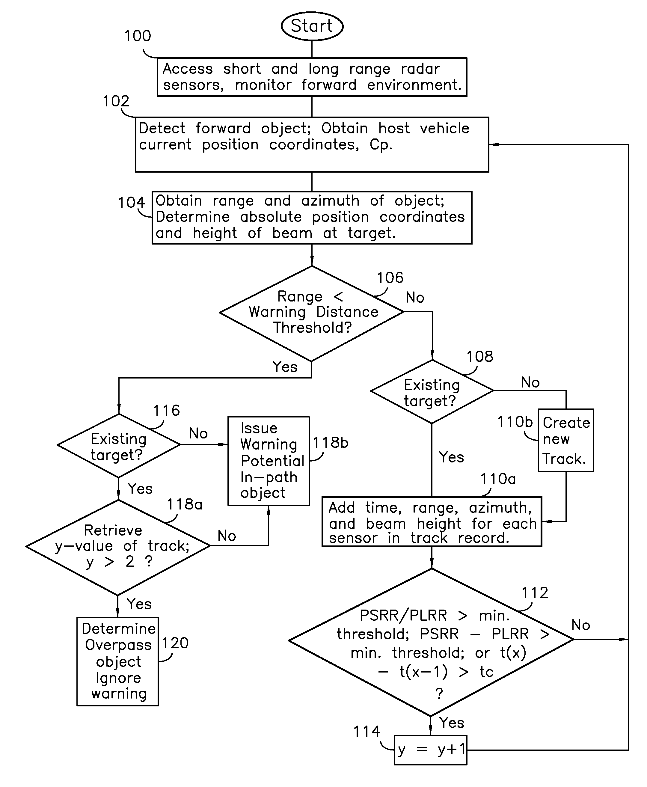
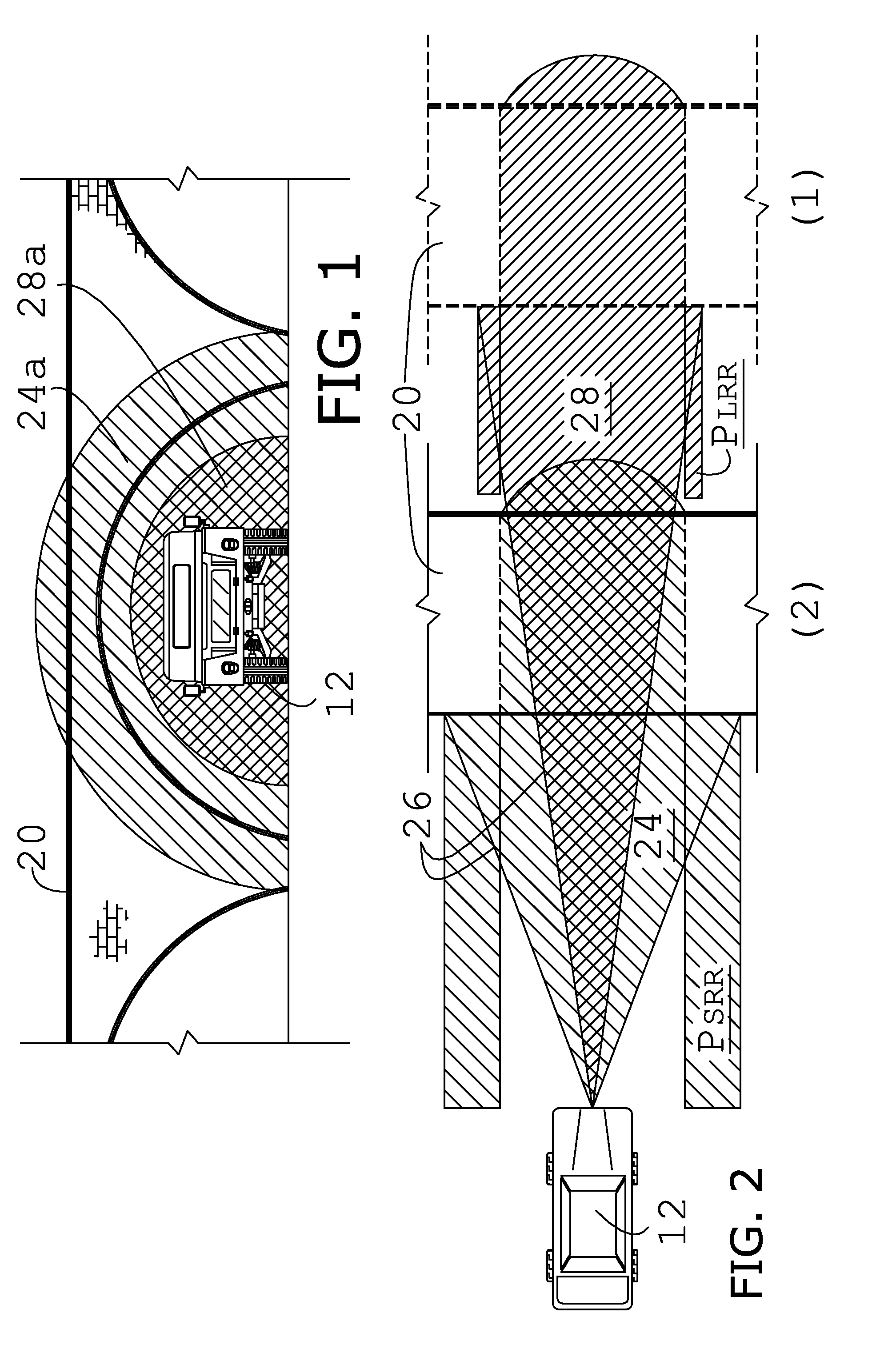
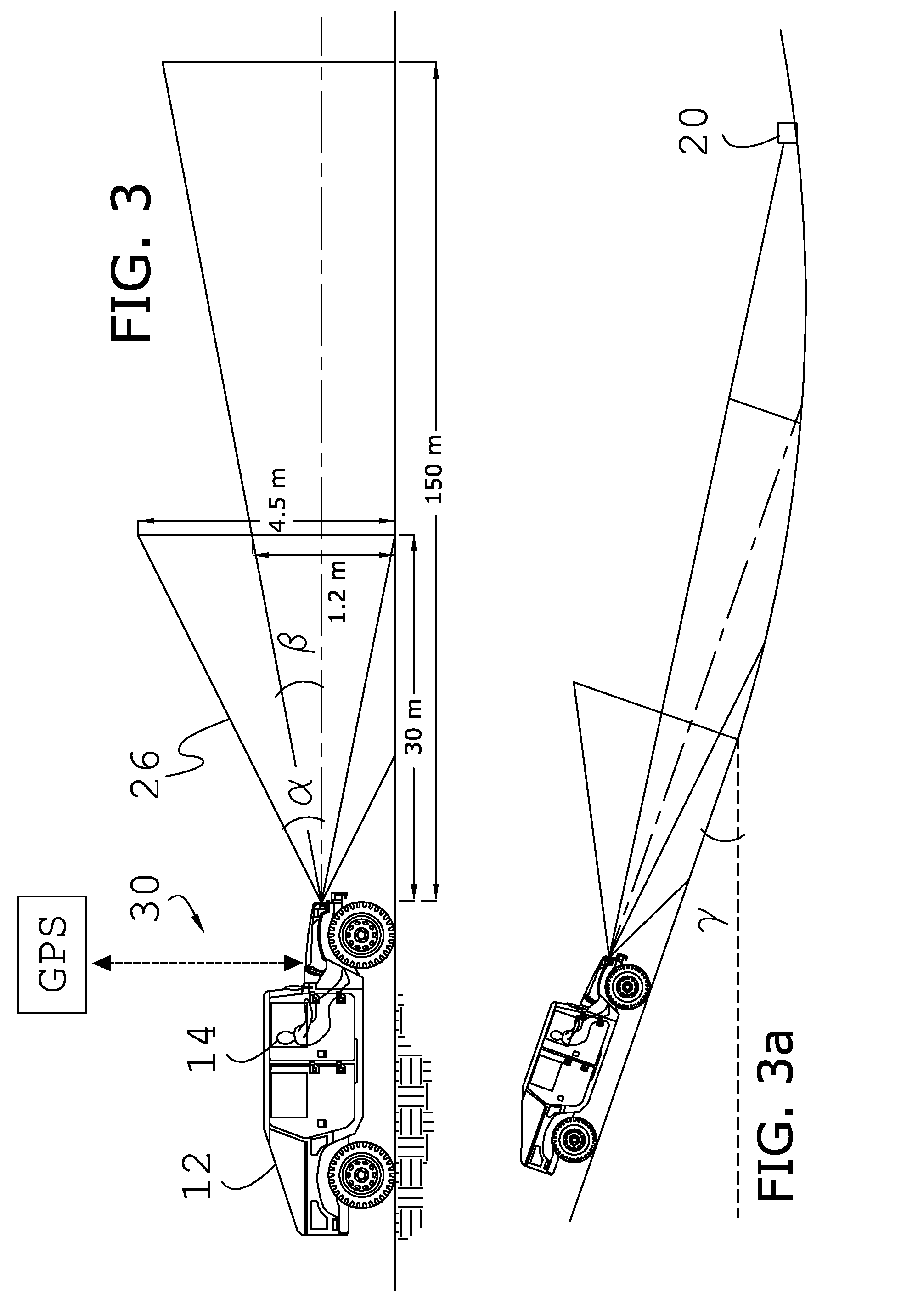
[0023]As shown in the illustrated embodiment, the present invention concerns a collision avoidance system 10 adapted for use with host vehicles 12, such as but not limited to automobiles, boats and aircrafts, and by an operator 14 (FIGS. 1 through 4). In general, the system 10 fuses the return signals of at least two radar sensors 16,18 to estimate elevation information for at least one target (or detected object) 20, such as the overpass shown in the illustrated embodiment.

[0024]As shown in FIG. 4, a digital fusion processor (DFP) 22 consists of an electronic control unit programmably equipped to perform the various algorithms and functions described herein, or more preferably, a plurality of communicatively coupled (i.e., connected by hard-wire or by a wireless communication sub-system) control units configured to perform parallel computations as part of a neural network. Alternatively, certain sub-routines may be performed by intermediate control units prior to delivery to the DF...


PUM


Abstract

A collision avoidance system for reducing false alerts by estimating the elevation of a target, includes short and long range single-dimensional scanning radar sensors having differing ranges and beam angles of inclination, and a digital fusion processor, and preferably includes a locator device, an inclinometer, and a memory storage device cooperatively configured to further perform trend analysis, and target tracking.

Description

BACKGROUND OF THE INVENTION[0001]1. Technical Field[0002]The present invention relates to collision avoidance and target identification systems and methods.[0003]2. Discussion of Prior Art[0004]Conventional collision avoidance and target identification systems typically employ the usage of radar technology, as radar continues to present a more facilely implementable and efficiently operable medium of detection. Both short-range radar (SRR) and long-range radar (LRR) enjoy wide application in many industries, such as automotive safety systems, and are often used in over-lapping configuration. In these systems, one or more laterally scanning sensors are oriented and configured to perform a single-dimensional scan of the surrounding environment, so as to detect surficial objects within an operable range. In some configurations, where an object is detected, a trend in the radar return signal strength over a period is assessed to determine whether the target (i.e., detected object) is ap...

Claims


Application Information

Patent Timeline
Patent Type & Authority Applications(United States)
IPC IPC(8): G01S13/93G01S13/06G01S13/931
CPCG01C9/00G01S13/42G01S2013/9321G01S13/931G01S2013/9375G01S13/87G01S2013/93271
Inventor COLBURN, JOSEPH S.ALTAN, OSMAN D.GEARY, KEVINHSU, HUI-PIN
Owner GM GLOBAL TECH OPERATIONS LLC
Why Eureka
Try Eureka