Antenna structures having adjustable radiation characteristics

a radiation characteristic and antenna technology, applied in the field of antennas, can solve the problems of sacrifice of antenna performance, achieve the effects of low profile, easy conformation or integration into complex surfaces, and promote near field electromagnetic energy coupling

Active Publication Date: 2009-01-01
GM GLOBAL TECH OPERATIONS LLC
View PDF15 Cites 43 Cited by
  • Summary
  • Abstract
  • Description
  • Claims
  • Application Information

AI Technical Summary

Benefits of technology

[0007]The applicants for the present invention have found that FSSs can be advantageously used to fabricate antenna structures having adjustable radiation characteristics. Broadly, this is accomplished by utilizing a FSS, which includes a patterned layer of conducting material having electromagnetic properties that vary as a function of frequency. An antenna element operating at a selected frequency is position proximate to the FSS to promote near field coupling of electromagnetic energy between the antenna element and the patterned layer of conducting material. The applicants have found that by structuring the patterned layer of conducting material to have specific electromagnetic properties at the selected frequency of operation of the antenna element, predetermined adjustments can be made to the radiation characteristics of the antenna structure. The direction, magnitude, and polarization of the radiation patterns of such antenna structures can be adjusted by varying the pattering or texture of the layer of conducting material forming the FSS.
[0008]Accordingly, the invention enables the fabrication of low profile antenna structures that can easily be conformed or integrated into complex surfaces. These aspects along with ability to adjust the radiation patterns of these antenna structures to accommodate their surrounding environment, makes their application particularly attractive for use on automotive vehicles.

Problems solved by technology

In order to make these antennas less conspicuous and preserve vehicle aesthetics and aerodynamics, it is often necessary to sacrifice antenna performance.

Method used


Image

  • Antenna structures having adjustable radiation characteristics
  • Antenna structures having adjustable radiation characteristics
  • Antenna structures having adjustable radiation characteristics

Examples


Embodiment Construction

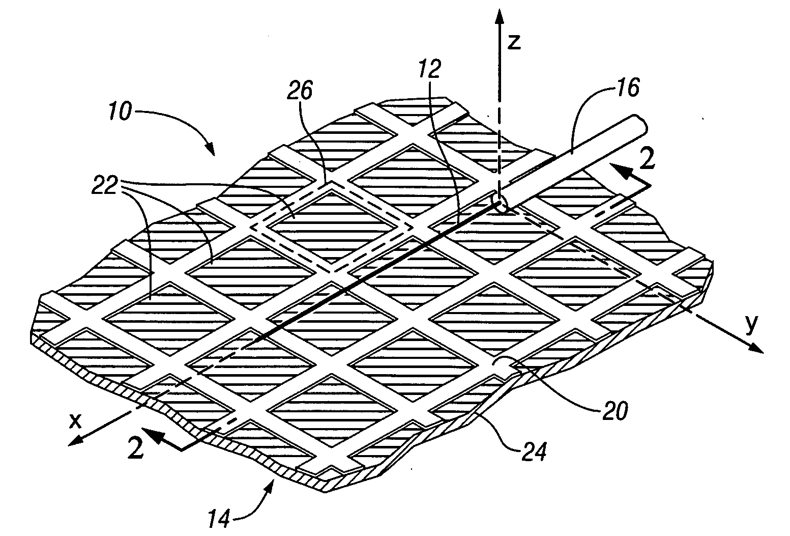
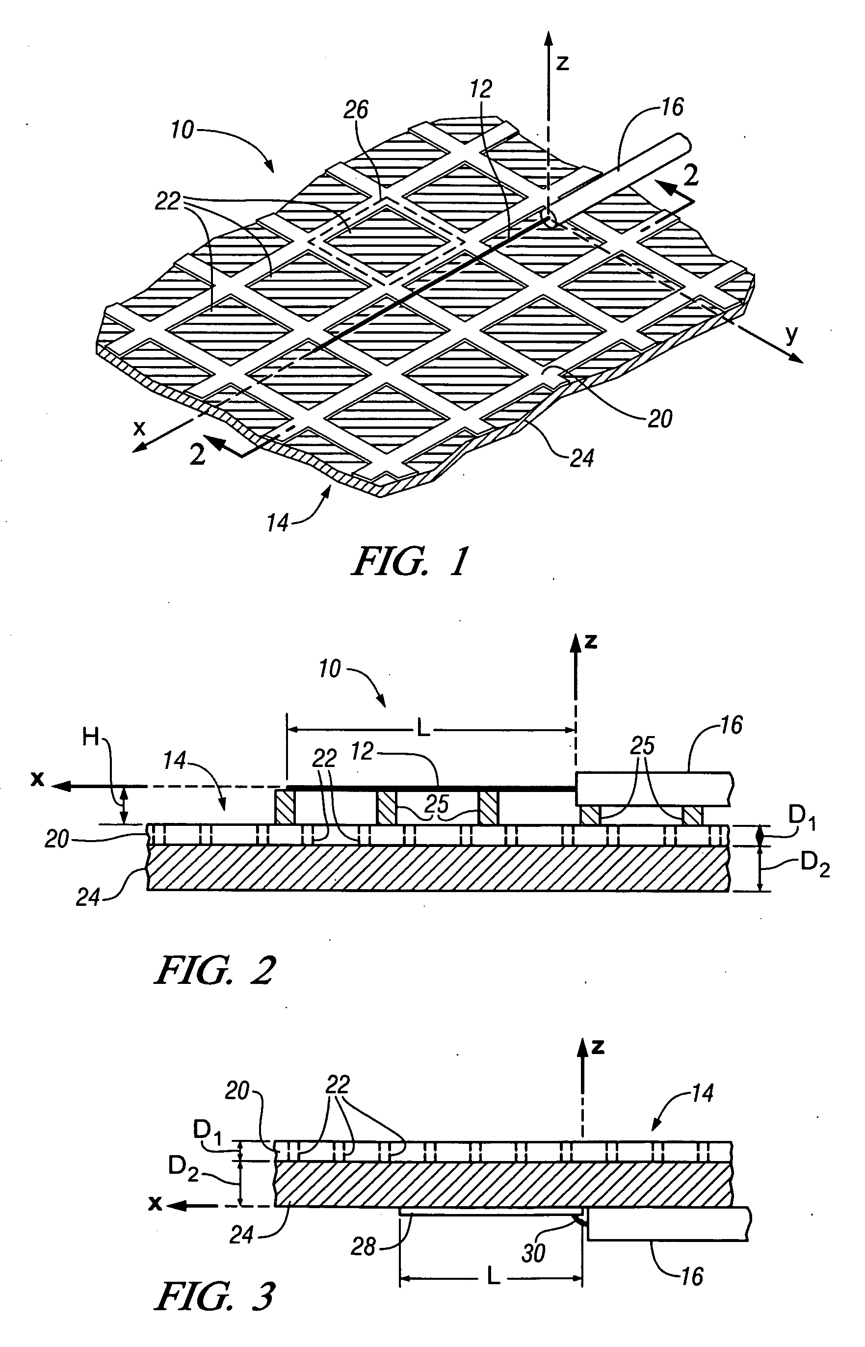
[0036]With reference first to FIG. 1, there is shown an antenna structure formed according to the present invention, which is designated generally as numeral 10. Antenna structure 10 includes an antenna element 12, positioned proximate a fragmented section of a frequency selective surface (FSS), generally designated as 14. For the embodiment of FIG. 1, FSS 14 is illustrated as being a planar surface; however, FSS 14 can also take the form of a curved surface or non-planar surface, as later described in the specification. The x, y, and z-axes of a rectangular coordinate system are also shown in FIG. 1, which will be used here, and throughout the specification for directional reference.

[0037]In this embodiment, antenna element 12 takes the form of a linear wire monopole antenna formed by the center wire conductor of coaxial cable 16, which is exposed after removing a portion of the shielding and outer cable covering. Antenna element 12 is shown as an elongate wire with its longitudina...


PUM


Abstract

The radiation properties and wave guiding properties of frequency selective surfaces are used in conjunction with closely spaced antenna elements to fabricate antenna structures having adjustable radiation characteristics. The direction, magnitude, and polarization of radiation patterns for such antenna structures can be adjusted by varying the texture or patterning of layers of conducting material forming the frequency selective surfaces. The invention enables the fabrication of low profile antenna structures that can easily be conformed or integrated into complex surfaces without sacrificing antenna performance.

Description

CROSS REFERENCE TO RELATED APPLICATIONS[0001]This is a division of U.S. patent application Ser. No. 11 / 327,122 entitled “ANTENNA STRUCTURES HAVING ADJUSTABLE RADIATION CHARACTERISTICS” filed on Jan. 6, 2006, and is also related to commonly assigned and co-pending U.S. patent application Ser. No. 11 / 326,881 (Attorney Docket No. GP-304621) also filed on Jan. 6, 2006, the contents of which are incorporated herein by reference.TECHNICAL FIELD[0002]The present invention is related to antennas, and more particularly to antenna structures utilizing frequency selective surfaces for the adjustment of antenna radiation characteristics.BACKGROUND OF THE INVENTION[0003]Over the past several years, the number of different information and entertainment (infotainment) services available for automotive use has dramatically increased. These services include AM / FM radio, cellular phones, GPS navigation, satellite radio, remote keyless entry, remote vehicle starting, and others. Each of these services...

Claims


Application Information

Patent Timeline
Patent Type & Authority Applications(United States)
IPC IPC(8): H01Q1/38
CPCH01Q15/0013H01Q9/30
Inventor SIEVENPIPER, DANIEL F.HSU, HUI-PIN
Owner GM GLOBAL TECH OPERATIONS LLC
Why Eureka
Try Eureka