Threaded anchor having a head portion comprising a hexagonally configured drive section, and an integral projection having a transverse bore formed therein

Inactive Publication Date: 2009-01-01
ILLINOIS TOOL WORKS INC
View PDF29 Cites 16 Cited by
  • Summary
  • Abstract
  • Description
  • Claims
  • Application Information

AI Technical Summary

Benefits of technology

[0005]The foregoing and other objectives are achieved in accordance with the teachings and principles of the present invention through the provision of a new and improved threaded anchor which comprises a threaded shank portion, having a large diameter thread portion and a small diameter thread portion wherein the plurality of threads comprising the small diameter thread portion are respectively interposed between the plurality of threads comprising the large diameter thread portion, a tip portion defined upon one end of the threaded shank portion and adapted to be inserted into a bore which has been pre-drilled into a masonry or concrete substrate or substructure, and a head portion disposed adjacent to the opposite end of the threaded shank portion. The head portion comprises a hexagonally configured drive section which serves as a drive means for threadedly driving, inserting, and embedding the threaded anchor within the pre-drilled bore defined within the masonry or concrete substrate or substructure, and an axially extending lug-type projection is integrally connected to the hexagonally configured drive section of the head portion. A transversely oriented throughbore is defined within the axially extending lug-type projection so as to accommodate structural or fixture support wires or cables, electrical power cables, fiber optic or telephone cables, turnbuckle wire assemblies, support straps, safety or guy wires, tie down wires or cables, and the like, and in this manner, not only can the single, integral, one-piece threaded anchor be rapidly installed within a particular masonry or concrete substrate or substructure, but in addition, the aforenoted cables, wires, straps, rods, or the like, can subsequently be easily and readily inserted into and through the bore, defined within the lug-type projection, so as to be secured to the lug-type projection of the threaded anchor.

Problems solved by technology

It is to be appreciated, however, that the anchor, as disclosed within the aforenoted patent, does not have the requisite structure that would en-able the same to be readily utilized in connection with the attachment, mounting, connection, securing, or supporting of the various aforenoted wires, cables, or support rods directly to the anchor.

Method used


Image

  • Threaded anchor having a head portion comprising a hexagonally configured drive section, and an integral projection having a transverse bore formed therein
  • Threaded anchor having a head portion comprising a hexagonally configured drive section, and an integral projection having a transverse bore formed therein
  • Threaded anchor having a head portion comprising a hexagonally configured drive section, and an integral projection having a transverse bore formed therein

Examples


Embodiment Construction

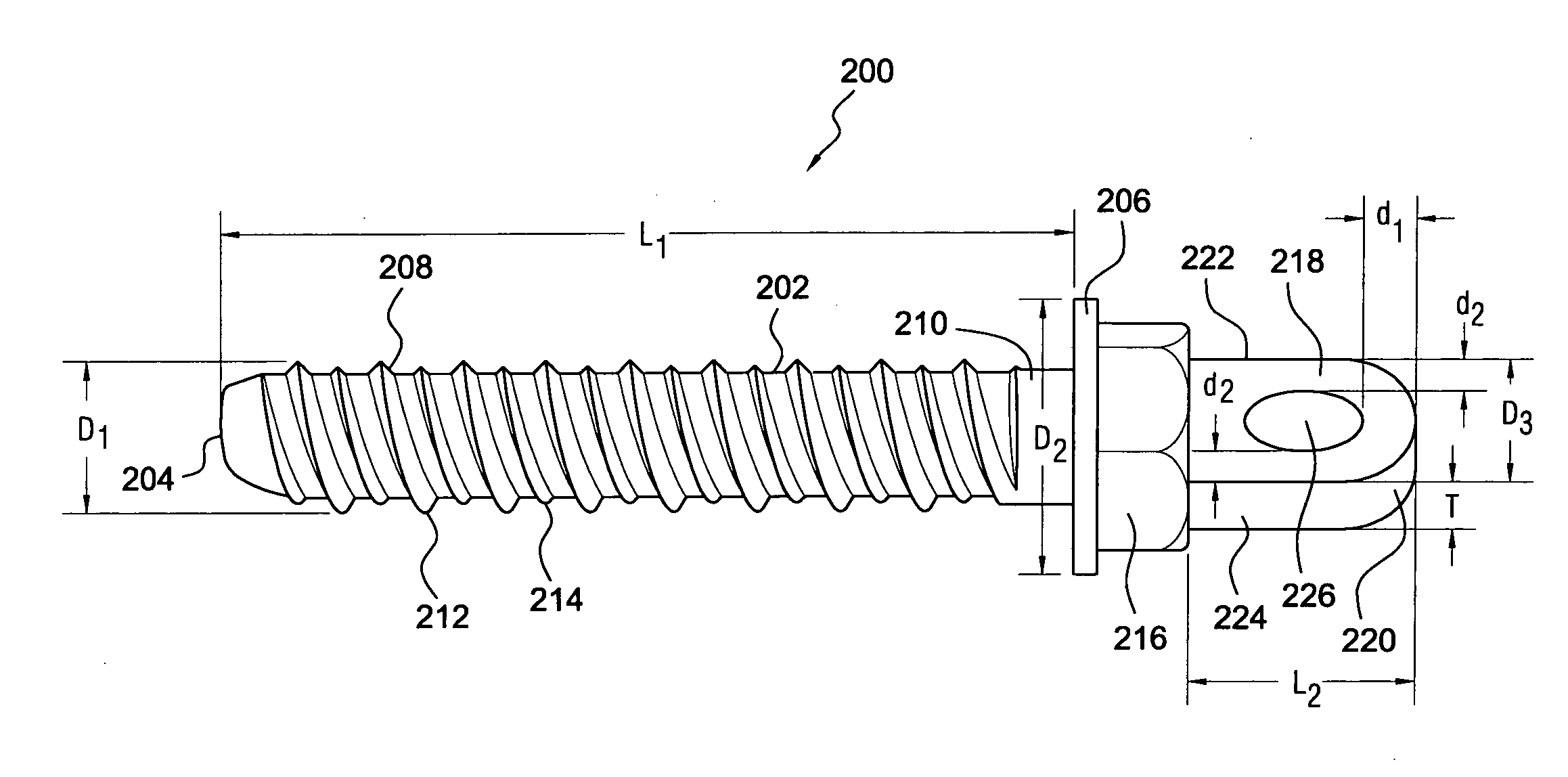
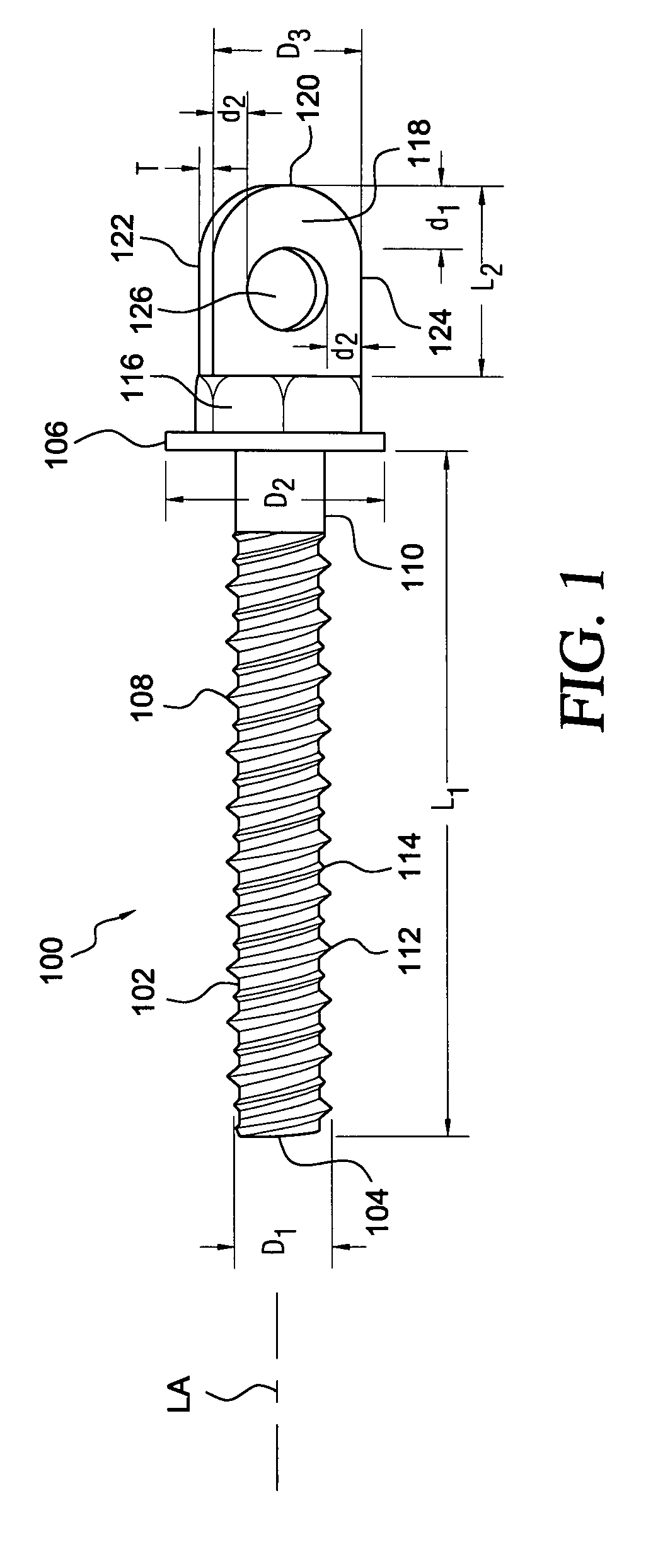
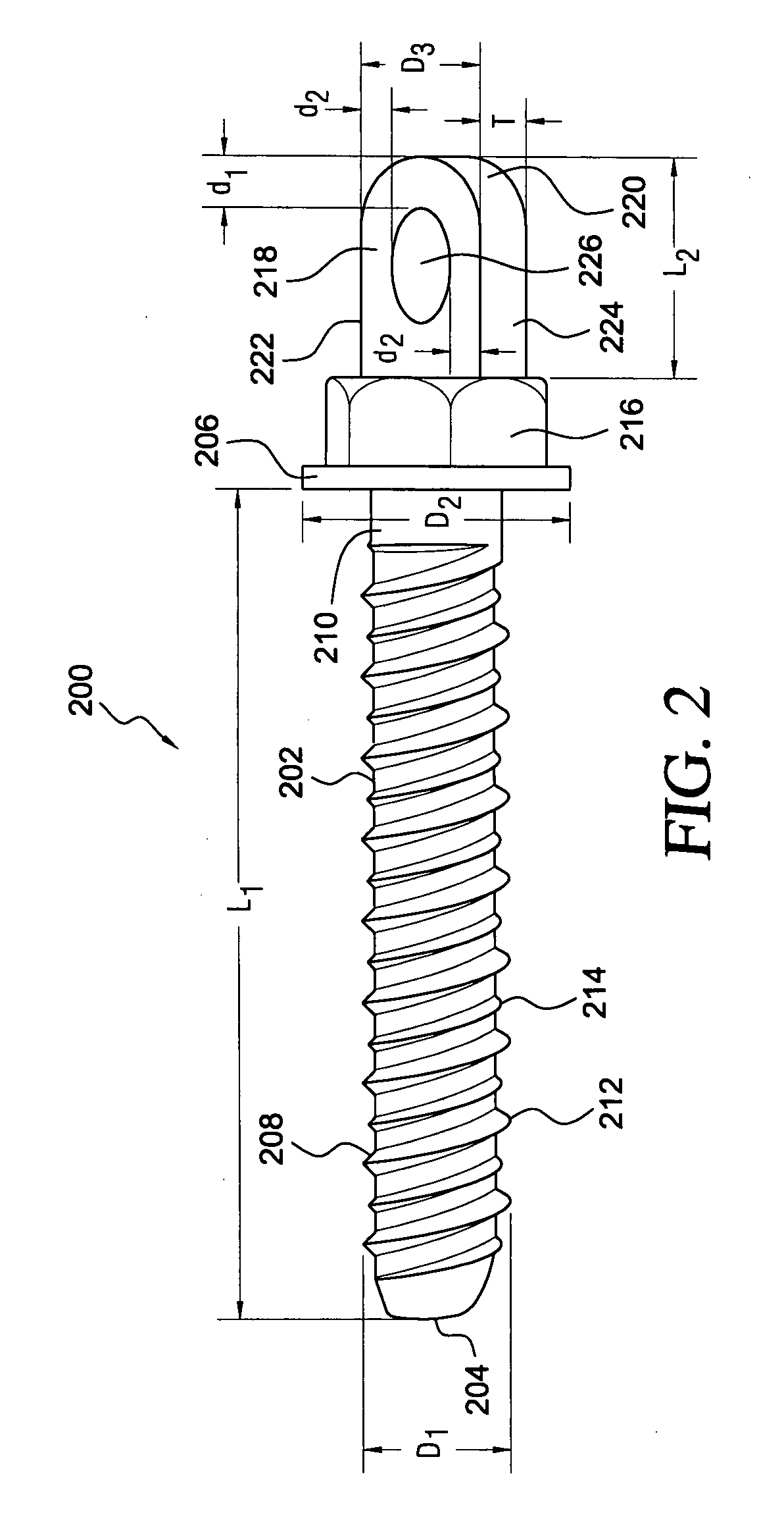
[0009]Referring now to the drawings, and more particularly to FIG. 1 thereof, a first embodiment of a new and improved threaded anchor, as constructed in accordance with the principles and teachings of the present invention and showing the cooperative parts thereof, is disclosed and is generally indicated by the reference character 100. More particularly, it is seen that the first embodiment of the new and improved threaded anchor 100, as constructed in accordance with the principles and teachings of the present invention, is seen to comprise a shank portion 102 which has a tip portion 104 formed upon a first axial end portion thereof, and a flanged head portion 106 formed upon a second opposite axial end portion thereof. The shank portion 102 of the threaded anchor 100 is seen to be threaded over a substantial axial extent thereof, wherein the threaded portion 108 of the threaded anchor 100 is seen to commence at substantially the first axial end tip portion 104 of the threaded anc...


PUM


Abstract

A threaded anchor which comprises a threaded shank portion, a tip portion defined upon one end of the threaded shank portion, and a head portion disposed adjacent to the opposite end of the threaded shank portion. The head portion comprises a hexagonally configured drive section for threadedly driving the threaded anchor into a substrate. An axially extending lug-type projection is integrally connected to the hexagonally configured drive section of the head portion, and a transversely oriented throughbore is defined within the axially extending lug-type projection so as to accommodate any one of a structural or fixture support wire or cable, a power cable, a fiber optic or telephone cable, a turnbuckle wire assembly, a support strap, a safety or guy wires, a tie down wire or cable, and the like.

Description

FIELD OF THE INVENTION[0001]The present invention relates generally to threaded anchors, and more particularly to a new and improved threaded anchor having a head portion integrally formed upon one end of the threaded anchor, wherein the head portion comprises a hexagonally configured drive section which serves as a drive means for threadedly driving, inserting, and embedding the threaded anchor within a bore which has been pre-drilled into a masonry or concrete substrate or substructure, wherein an axially extending lug-type projection is integrally connected to the hexagonally configured drive section of the head portion, and wherein further, a transversely oriented throughbore is defined within the lug-type projection so as to accommodate structural or fixture support wires or cables, electrical power cables, fiber optic or telephone cables, turnbuckle wire assemblies, support straps, safety or guy wires, tie down wires or cables, threaded support rods, and the like. In this mann...

Claims


Application Information

Patent Timeline
Patent Type & Authority Applications(United States)
IPC IPC(8): F16B25/08
CPCF16B25/0026F16B25/0068F16B45/00F16B35/06F16B25/10
Inventor GRIFFITH, RICHARD
Owner ILLINOIS TOOL WORKS INC
Why Eureka
Try Eureka