
Transmit beamforming in 3-dimensional ultrasound

a technology of ultrasound and beamforming, applied in the field of ultrasound medical imaging systems, can solve problems such as significant heat generation

Active Publication Date: 2009-01-01
GENERAL ELECTRIC CO
View PDF14 Cites 86 Cited by
  • Summary
  • Abstract
  • Description
  • Claims
  • Application Information

AI Technical Summary

Problems solved by technology

Some probes use transmitters located within the probe although this configuration can generate significant heat.

Method used


Image

  • Transmit beamforming in 3-dimensional ultrasound
  • Transmit beamforming in 3-dimensional ultrasound
  • Transmit beamforming in 3-dimensional ultrasound

Examples


Embodiment Construction

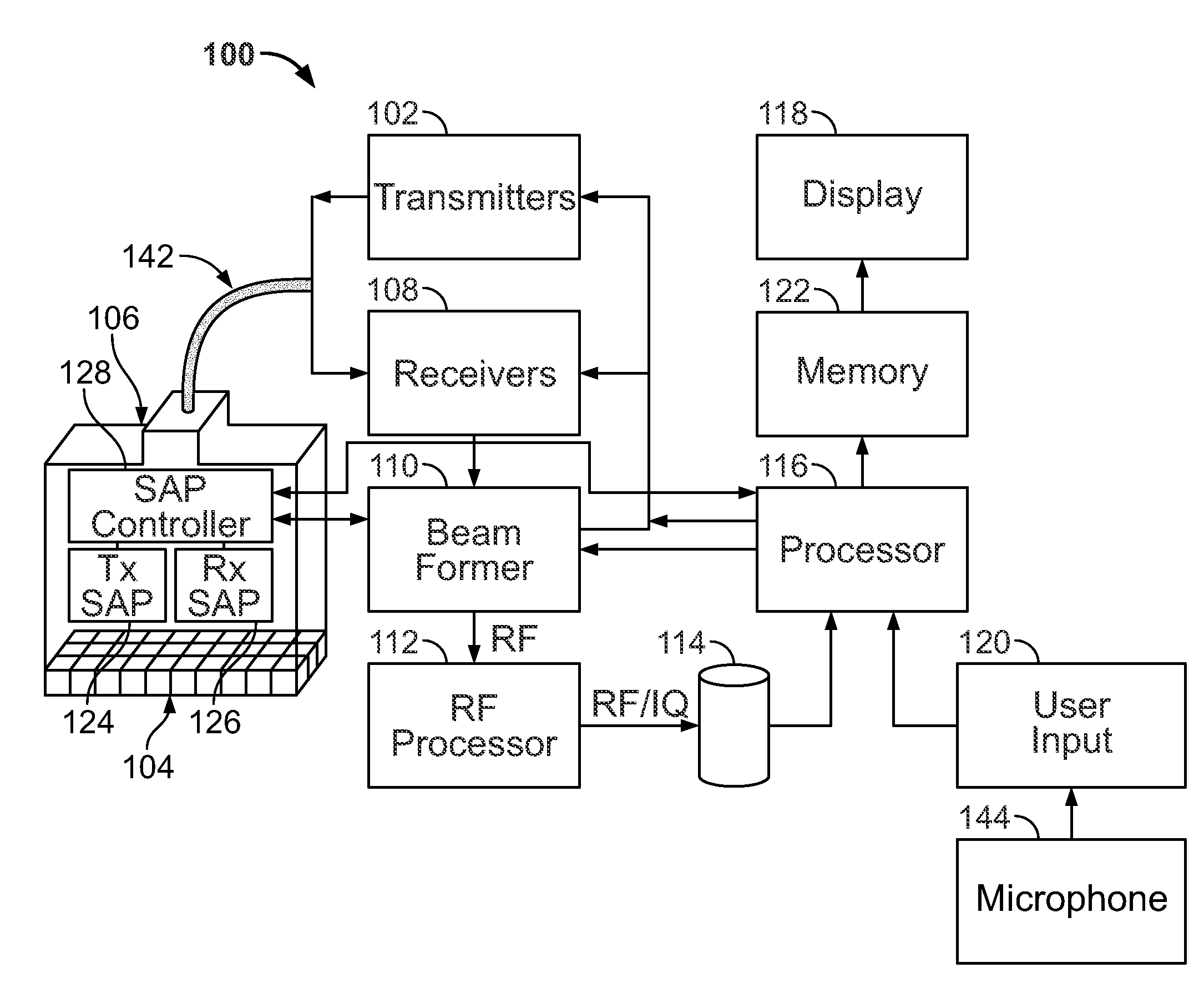
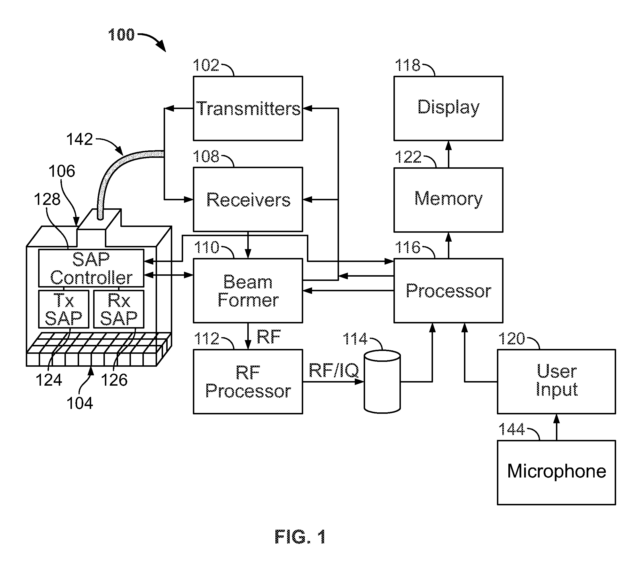
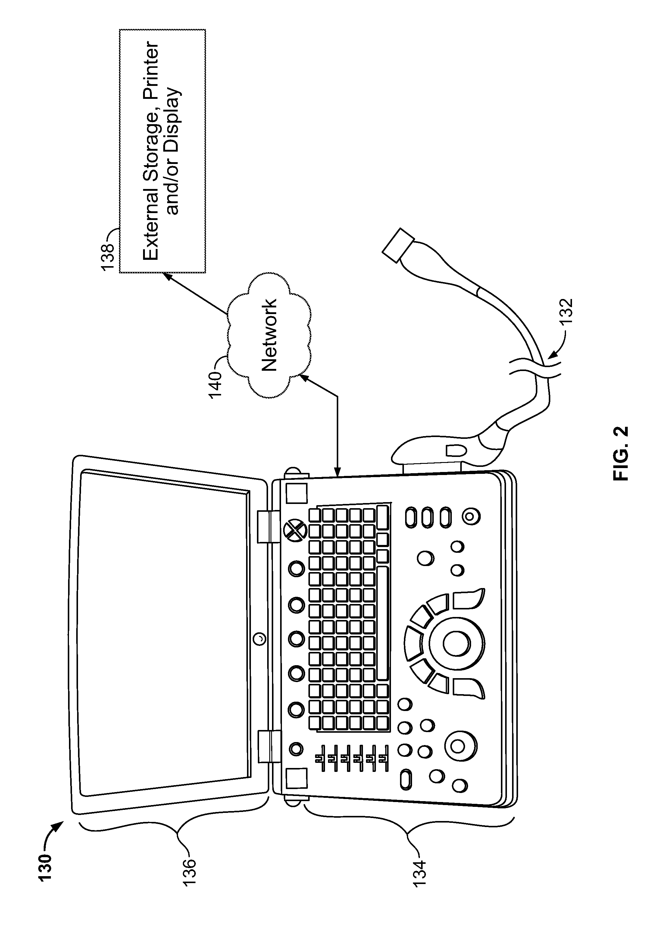
[0024]The foregoing summary, as well as the following detailed description of certain embodiments of the present invention, will be better understood when read in conjunction with the appended drawings. To the extent that the figures illustrate diagrams of the functional blocks of various embodiments, the functional blocks are not necessarily indicative of the division between hardware circuitry. Thus, for example, one or more of the functional blocks (e.g., processors or memories) may be implemented in a single piece of hardware (e.g., a general purpose signal processor or random access memory, hard disk, or the like). Similarly, the programs may be stand alone programs, may be incorporated as subroutines in an operating system, may be functions in an installed software package, and the like. It should be understood that the various embodiments are not limited to the arrangements and instrumentality shown in the drawings.

[0025]FIG. 1 illustrates a block diagram of an ultrasound sys...


PUM


Abstract

An ultrasound system comprises a probe including a two-dimensional (2D) array of transducer elements that form an aperture having a plurality of receive elements that are configured to receive ultrasound signals. The transducer elements form at least one transmit sub-aperture that is configured to be interconnected with a fixed group of the transducer elements within the aperture. Transmitters generate electrical transmit signals, and at least one transmit sub-aperture processor (tx SAP) maps the transducer elements within the fixed group of the transducer elements to the transmitters in a transmit configuration based on a beam steering direction.

Description

BACKGROUND OF THE INVENTION[0001]This invention relates generally to ultrasound medical imaging systems, and more specifically, to partitioning multiple transducer elements of an ultrasonic probe into non-overlapping sub-apertures for the transmission of an ultrasound signal.[0002]Two key components of an ultrasound system are the ultrasound probe and the beamformer. The beamformer focuses and steers ultrasound energy transmitted by and received by the probe to acquire image data, and as one step in generating images of anatomic content on a display. Three-dimensional (3D) ultrasound imaging may be accomplished using a probe that has a two-dimensional (2D) matrix array of transducer elements. In many systems, the elements are used for both transmit and receive operations. Current systems achieve this dual operation of the transducer elements by multiplexing between the transmit and receive circuitry in the system. Each channel in the probe may be connected with one cable to the syst...

Claims


Application Information

Patent Timeline
IPC IPC(8): A61B8/00
CPCA61B8/4461A61B8/4483G03B42/06G01S15/8925G01S15/8927A61B8/483A61B8/4494A61B8/4488B06B2201/76
Inventor KRISTOFFERSEN, KJELLHAIDER, BRUNO HANSHALVORSROED, THOMASBJAERUM, STEINAR
Owner GENERAL ELECTRIC CO
Features
  • Generate Ideas
  • Intellectual Property
  • Life Sciences
  • Materials
  • Tech Scout
  • Unparalleled Data Quality
  • Higher Quality Content
  • 60% Fewer Hallucinations
Learn More