DMA transfer control device and method of DMA transfer

Inactive Publication Date: 2009-01-01
RENESAS ELECTRONICS CORP
View PDF2 Cites 9 Cited by
  • Summary
  • Abstract
  • Description
  • Claims
  • Application Information

AI Technical Summary

Benefits of technology

[0024]According to the configuration or the method described above, it is possible to repeat the fixed-length burst transfer without paying attention to the page boundaries. Special processing such as interrupting a burst transfer operation is not necessary at a page boundary. Moreover, the undefined-length burst transfer that is accompanied by the overheads needs not be performed at every page boundary. Therefore, the overheads at every page boundary are eliminated and thereby the deterioration of the data transfer efficiency can be prevented. Even in a case where large volume data need to be transferred and hence a large number of page boundary crossings occur during the data transfer, the data transfer efficiency can be maintained.

Problems solved by technology

However, a burst transfer that crosses (strides across) a page boundary between two pages is not permitted in the SDRAM.
This deteriorates the data transfer efficiency, which is the problem.
The undefined-length burst transfer and its overhead increase in proportion to the number of times. Therefore, the data transfer efficiency is deteriorated as the size of the transfer data is increased.

Method used


Image

  • DMA transfer control device and method of DMA transfer
  • DMA transfer control device and method of DMA transfer
  • DMA transfer control device and method of DMA transfer

Examples


first embodiment

1. First Embodiment

1-1. Configuration

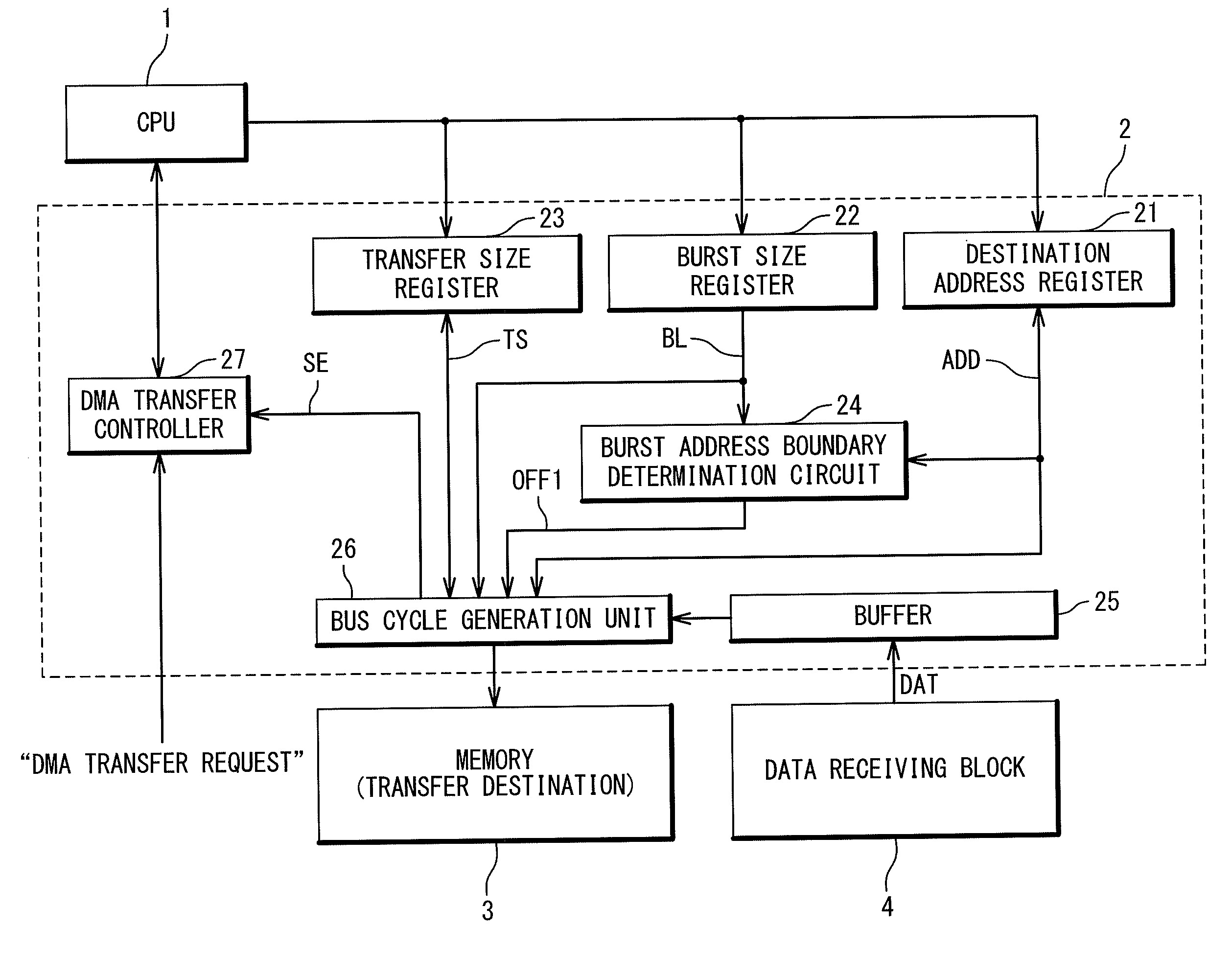
[0036]FIG. 3 is a block diagram showing a configuration of a data processing equipment according to a first embodiment of the present invention. The data processing equipment is provided with a CPU 1, a DMA transfer control device 2, a memory 3 and a data receiving block 4. The CPU 1, the DMA transfer control device 2, the memory 3 and the data receiving block 4 are connected to each other through a bus.

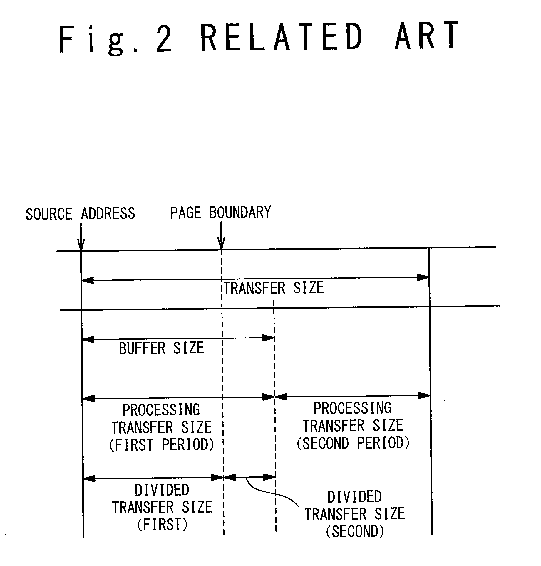
[0037]The memory 3 is, for example, an SDRAM that supports the burst mode and has a plurality of pages. One page is a memory area of a predetermined size such as 512 bytes, 1 Kbytes or 2 Kbytes. One page in the memory 3 is accessed by plural burst transfers and includes a plurality of burst address boundaries. In the present embodiment, a DMA transfer to the memory 3 will be described. That is to say, the memory 3 is a “transfer destination” of the data transfer.

[0038]On the other hand, the data receiving block 4 is a “transfer source” of the data...

second embodiment

2. Second Embodiment

2-1. Configuration

[0073]FIG. 6 is a block diagram showing a configuration of a data processing equipment according to a second embodiment of the present invention. In FIG. 6, the same reference numerals are given to the same components as those described in the first embodiment, and an overlapping description will be omitted as appropriate. The DMA transfer control device 2 according to the second embodiment includes a word address boundary determination circuit 28 in addition to the configuration shown in FIG. 3.

[0074]The word address boundary determination circuit 28 reads the destination address ADD from the destination address register 21. Based on the destination address ADD and the data bus width, the word address boundary determination circuit 28 calculates a “word offset value OFF2” that is an offset from the destination address ADD to a word address boundary that comes first after the destination address ADD. Here, the word address boundary means a bound...

third embodiment

3. Third Embodiment

3-1. Configuration

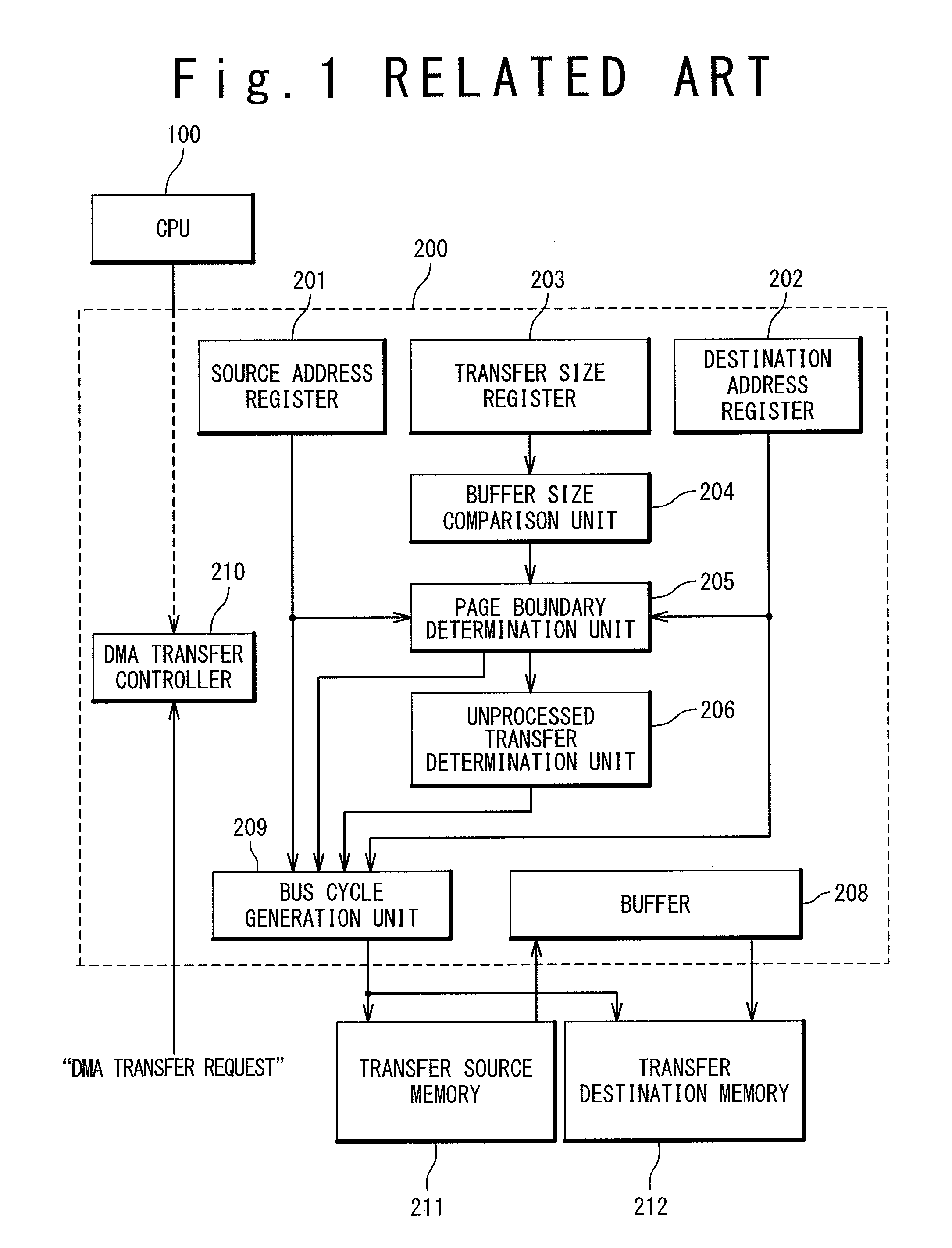
[0087]FIG. 8 is a block diagram showing a configuration of a data processing equipment according to a third embodiment of the present invention. In FIG. 8, the same reference numerals are given to the same components as those described in the first embodiment, and an overlapping description will be omitted as appropriate. The DMA transfer control device 2 according to the third embodiment includes a transfer completion code detection circuit 29 in addition to the configuration shown in FIG. 3. Moreover, the transfer size register 23 is eliminated from the DMA transfer control device 2.

[0088]The transfer completion code detection circuit 29 detects a specific transfer completion code from the transfer data DAT stored in the buffer 25. The transfer completion code indicates transfer completion of the transfer data DAT. For example, the transfer completion code is calculated from data sequence in the transfer data DAT, and only one kind exists. When...


PUM


Abstract

A DMA transfer control device for controlling a DMA transfer between a source and a destination is provided. The DMA transfer control device has: a buffer in which a transfer data is stored; and a bus cycle generation unit performing a burst transfer of the transfer data between the buffer and the source or the destination. The bus cycle generation unit performs an undefined-length burst transfer until an access address reaches a burst address boundary in the source or the destination. The bus cycle generation unit performs a fixed-length burst transfer after the undefined-length burst transfer until transfer of the transfer data is completed.

Description

INCORPORATION BY REFERENCE[0001]This application is based upon and claims the benefit of priority from Japanese patent application No. 2007-167265, filed on Jun. 26, 2007, the disclosure of which is incorporated herein in its entirely by reference.BACKGROUND OF THE INVENTION[0002]1. Field of the Invention[0003]The present invention relates to a DMA transfer technique. In particular, the present invention relates to a technique of controlling a DMA transfer that uses a burst transfer.[0004]2. Description of Related Art[0005]A high-speed memory such as an SDRAM (Synchronous Dynamic Random Access Memory) is equipped with a burst mode that performs a “burst transfer”, in order to achieve a high-speed data transfer. In the burst transfer, a starting address of consecutive addresses is specified and then data reading or data writing are sequentially executed from the starting address (refer to Japanese Laid-Open Patent Application JP-2005-141682, for example).[0006]Moreover, a “DMA (Direc...

Claims


Application Information

Patent Timeline
IPC IPC(8): G06F13/28
CPCG06F13/28
Inventor TOYAMA, KEIICHIWU, WEIYUSAKUMA, YUKIYAWATANABE, KATSUMI
Owner RENESAS ELECTRONICS CORP
Why Eureka
Try Eureka